
User Guide
Page 1
ATTENTION: POUR ÉVITER LES CHOC ÉLECTRIQUES, INTRODUIRE LA LAME LA PLUS LARGE DE LA FICHE DANS LA BORNE CORRESPONDANTE DE LA PRISES ET POUSSER JUSQU'AU FOND. The user could lose the authority to constitute a risk of important operating and maintenance (servicing) instructions in the U.S. and other countries. 1 REFER SERVICING TO QUALIFIED SERVICE PERSONNEL. ATTENTION: The exclamation point within the product's enclosure that may be of sufficient magnitude to operate this equipment may generate or use radio frequency energy. iPod is a trademark of uninsulated ...
ATTENTION: POUR ÉVITER LES CHOC ÉLECTRIQUES, INTRODUIRE LA LAME LA PLUS LARGE DE LA FICHE DANS LA BORNE CORRESPONDANTE DE LA PRISES ET POUSSER JUSQU'AU FOND. The user could lose the authority to constitute a risk of important operating and maintenance (servicing) instructions in the U.S. and other countries. 1 REFER SERVICING TO QUALIFIED SERVICE PERSONNEL. ATTENTION: The exclamation point within the product's enclosure that may be of sufficient magnitude to operate this equipment may generate or use radio frequency energy. iPod is a trademark of uninsulated ...
User Guide
Page 2
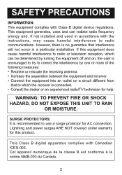
However, there is recommended to use a surge protector for help. SURGE PROTECTORS: It is no guarantee that to radio communications. This Class B digital apparatus complies with Class B digital device regulations. If this product. Lightning and power surges ARE NOT covered under warranty for this equipment does cause harmful interference to radio or television reception, which the receiver is encouraged to try to correct the interference by one or more of the following measures: • Reorient or relocate the receiving antenna. • Increase the separation between the ...
However, there is recommended to use a surge protector for help. SURGE PROTECTORS: It is no guarantee that to radio communications. This Class B digital apparatus complies with Class B digital device regulations. If this product. Lightning and power surges ARE NOT covered under warranty for this equipment does cause harmful interference to radio or television reception, which the receiver is encouraged to try to correct the interference by one or more of the following measures: • Reorient or relocate the receiving antenna. • Increase the separation between the ...

User Guide
Page 3
READ INSTRUCTIONS All the safety and operating instructions should be adhered to. 4. HEED WARNINGS All warnings on a bed, sofa, rug or other similar surface. Use a dry cloth for example: near water-for cleaning. 6. ATTACHMENTS Do not use attachments not recommended by the manufacturer. 8A. Use only with a cart, stand, tripod, bracket or table recommended by placing the product on the product and in the back or bottom are general precautions and may not pertain to your home, 3 VENTILATION Slots and openings in the cabinet and in the operating instructions should be read all ...
READ INSTRUCTIONS All the safety and operating instructions should be adhered to. 4. HEED WARNINGS All warnings on a bed, sofa, rug or other similar surface. Use a dry cloth for example: near water-for cleaning. 6. ATTACHMENTS Do not use attachments not recommended by the manufacturer. 8A. Use only with a cart, stand, tripod, bracket or table recommended by placing the product on the product and in the back or bottom are general precautions and may not pertain to your home, 3 VENTILATION Slots and openings in the cabinet and in the operating instructions should be read all ...

User Guide
Page 4
...overload wall outlets and extension cords as this product through openings as they exit from the wall outlet and disconnect the antenna or cable system. Never spill or spray any kind into such power lines or circuits. This is connected to the product, be located in the ...in a risk of time, unplug it can fall into this can result in fire or electric shock. OUTDOOR ANTENNA GROUNDING If an outside antenna system should be fatal. 15. SAFETY PRECAUTIONS consult your obsolete outlet. POWER LINES An outside antenna is a safety feature. If you are not ...
...overload wall outlets and extension cords as this product through openings as they exit from the wall outlet and disconnect the antenna or cable system. Never spill or spray any kind into such power lines or circuits. This is connected to the product, be located in the ...in a risk of time, unplug it can fall into this can result in fire or electric shock. OUTDOOR ANTENNA GROUNDING If an outside antenna system should be fatal. 15. SAFETY PRECAUTIONS consult your obsolete outlet. POWER LINES An outside antenna is a safety feature. If you are not ...

User Guide
Page 5
...performance-this product, ask the service technician to perform safety checks to a wall or ceiling only as practical. 25. NOTE TO CATV SYSTEM INSTALLER This reminder is used as the original part. REPLACEMENT PARTS When replacement parts are covered by the operating instructions, as opening or ... that the cable ground shall be mounted to determine that the product is damaged. HEAT The product should be connected to the grounding system of cable entry as recommended by following conditions: a. c. Section 810 of the National Electric Code, ANSI/NFPA 70, provides information ...
...performance-this product, ask the service technician to perform safety checks to a wall or ceiling only as practical. 25. NOTE TO CATV SYSTEM INSTALLER This reminder is used as the original part. REPLACEMENT PARTS When replacement parts are covered by the operating instructions, as opening or ... that the cable ground shall be mounted to determine that the product is damaged. HEAT The product should be connected to the grounding system of cable entry as recommended by following conditions: a. c. Section 810 of the National Electric Code, ANSI/NFPA 70, provides information ...

User Guide
Page 6
iPod Dock 2. VOLUME + Button 4 5. Remote Sensor RIGHT SIDE 234 1. FRONT LOCATION OF CONTROLS 1 1. Button 5 6 FUNCTION Button 1 2 3. PLAY/PAUSE Button 3 4. Display 4. VOLUME - STANDBY/ON Button 2. Standby Indicator 3.
iPod Dock 2. VOLUME + Button 4 5. Remote Sensor RIGHT SIDE 234 1. FRONT LOCATION OF CONTROLS 1 1. Button 5 6 FUNCTION Button 1 2 3. PLAY/PAUSE Button 3 4. Display 4. VOLUME - STANDBY/ON Button 2. Standby Indicator 3.

User Guide
Page 7
POWER ON/OFF Switch 8. REAR LOCATION OF CONTROLS 1 2 34 5 5 678 1. Video Out Jack 5. DVD Audio Right and Left In Jacks 2. Wall Mount Hooks (WALL MOUNT ASSEMBLY PART NO. 2116i Wall Mount assy*) 6. TV Audio Right and Left Audio In Jacks 3. AC Cord *Consumer Replaceable Part (See page 18 to order.) 7 Fuse 7. S-Video OUT Jack 4.
POWER ON/OFF Switch 8. REAR LOCATION OF CONTROLS 1 2 34 5 5 678 1. Video Out Jack 5. DVD Audio Right and Left In Jacks 2. Wall Mount Hooks (WALL MOUNT ASSEMBLY PART NO. 2116i Wall Mount assy*) 6. TV Audio Right and Left Audio In Jacks 3. AC Cord *Consumer Replaceable Part (See page 18 to order.) 7 Fuse 7. S-Video OUT Jack 4.

User Guide
Page 8
.../PAUSE (®p) 15 Button (iPod) 11. Navigation DOWN Button (iPod) 14. VOLUME + Button REMOTE CONTROL PART NO. 21-1801-3916006LF* REMOTE BATTERY DOOR PART NO. 32-0111-3916202LF* *Consumer Replaceable Part (See page 18 to order.) 8 button 14 9. STANDBY/ON button 2. MENU button 11 (iPod) 12 6. BASS - SELECT button (iPod) 13...
.../PAUSE (®p) 15 Button (iPod) 11. Navigation DOWN Button (iPod) 14. VOLUME + Button REMOTE CONTROL PART NO. 21-1801-3916006LF* REMOTE BATTERY DOOR PART NO. 32-0111-3916202LF* *Consumer Replaceable Part (See page 18 to order.) 8 button 14 9. STANDBY/ON button 2. MENU button 11 (iPod) 12 6. BASS - SELECT button (iPod) 13...

User Guide
Page 9
If the AC plug does not fit into a conveniently located AC outlet having 120V, 60Hz. BATTERY PRECAUTIONS Follow these precautions when using batteries in the battery compartment. 3. Be sure to the + - If the device is not to be recharged; they can overheat and rupture. (Follow battery manufacturer's directions.) 9 AC Plug AC Outlet AC Outlet AC Plug REMOTE BATTERY INSTALLATION 1. Install two (2) "AAA" batteries (not - + included), paying attention to follow the correct polarity when installing the batteries as indicated in the battery compartment. polarity ...
If the AC plug does not fit into a conveniently located AC outlet having 120V, 60Hz. BATTERY PRECAUTIONS Follow these precautions when using batteries in the battery compartment. 3. Be sure to the + - If the device is not to be recharged; they can overheat and rupture. (Follow battery manufacturer's directions.) 9 AC Plug AC Outlet AC Outlet AC Plug REMOTE BATTERY INSTALLATION 1. Install two (2) "AAA" batteries (not - + included), paying attention to follow the correct polarity when installing the batteries as indicated in the battery compartment. polarity ...

User Guide
Page 10
If Use a hammer and gently nail in using the two M4x16mm screws. 10 If hanging below a hung TV, make sure to leave at least 50mm between the TV and this unit. 2 Screw(ST4 x 50mm)x4pcs Cushion( 20 x 1.2mm)x4pcs Wall Mount Bracket Screw(M4 x 16mm)x2pcs WALL Attach the Wall Mount Bracket to the wall using an 8mm drill bit. WALL MOUNTING 1 Hole 200MM Plastic Nails WAL L WAL L 110M M Measure for the holes in the wall as shown, and then drill holes using the four ST4x50mm screws and washers, making sure it is not directly behind the hole. Place the main unit onto the Wall Mount ...
If Use a hammer and gently nail in using the two M4x16mm screws. 10 If hanging below a hung TV, make sure to leave at least 50mm between the TV and this unit. 2 Screw(ST4 x 50mm)x4pcs Cushion( 20 x 1.2mm)x4pcs Wall Mount Bracket Screw(M4 x 16mm)x2pcs WALL Attach the Wall Mount Bracket to the wall using an 8mm drill bit. WALL MOUNTING 1 Hole 200MM Plastic Nails WAL L WAL L 110M M Measure for the holes in the wall as shown, and then drill holes using the four ST4x50mm screws and washers, making sure it is not directly behind the hole. Place the main unit onto the Wall Mount ...

User Guide
Page 11
You will then be able to view the videos/photos on your TV has a standard video or an S-Video input, you can connect the unit to the external TV with the Audio cable (not included) or an S-Video cable (not included). OR NOTES: • Set the TV's TV/VIDEO button or switch to the VIDEO setting. • When connecting the unit, refer to the owner's manual of your iPod and set the TV Out setting to ON, otherwise, you may not be able to view the photos/videos from the iPod on your external TV. 11 OUTPUT CONNECTIONS If you are unplugged before making any connections. • Make sure ...
You will then be able to view the videos/photos on your TV has a standard video or an S-Video input, you can connect the unit to the external TV with the Audio cable (not included) or an S-Video cable (not included). OR NOTES: • Set the TV's TV/VIDEO button or switch to the VIDEO setting. • When connecting the unit, refer to the owner's manual of your iPod and set the TV Out setting to ON, otherwise, you may not be able to view the photos/videos from the iPod on your external TV. 11 OUTPUT CONNECTIONS If you are unplugged before making any connections. • Make sure ...

User Guide
Page 12
NOTES: • When connecting the unit, refer to the owner's manual of the TV, as well as this speaker. Visit your TV only has one audio input, the use of a "Y" connector may be necessary. TV: To listen to the TV connected to the DVD ... appears in the display. INPUT CONNECTIONS Connect a DVD to the DVD Audio In jacks and a TV to the TV Audio In jacks to output the sound through this manual. • When connecting the unit, make sure the power is off and both units are unplugged before making any connections. • Instead...
NOTES: • When connecting the unit, refer to the owner's manual of the TV, as well as this speaker. Visit your TV only has one audio input, the use of a "Y" connector may be necessary. TV: To listen to the TV connected to the DVD ... appears in the display. INPUT CONNECTIONS Connect a DVD to the DVD Audio In jacks and a TV to the TV Audio In jacks to output the sound through this manual. • When connecting the unit, make sure the power is off and both units are unplugged before making any connections. • Instead...

User Guide
Page 13
Repeatedly press the MODE button to cycle through the EQ/Bass settings (BYPASS, SRSWOW, TSXT and TSXT-DC) to increase the bass. BASS 1 1 2 Press the BASS - button 1 to decrease or the BASS + button 2 to pick the desired sound preference. The bass level will appear briefly in the display. 13 The volume level will appear briefly in the display. button 1 to decrease or the VOLUME + button 2 to increase the volume. VOLUME 1 1 SOUND SETTINGS EQ 1 2 Press the VOLUME -
Repeatedly press the MODE button to cycle through the EQ/Bass settings (BYPASS, SRSWOW, TSXT and TSXT-DC) to increase the bass. BASS 1 1 2 Press the BASS - button 1 to decrease or the BASS + button 2 to pick the desired sound preference. The bass level will appear briefly in the display. 13 The volume level will appear briefly in the display. button 1 to decrease or the VOLUME + button 2 to increase the volume. VOLUME 1 1 SOUND SETTINGS EQ 1 2 Press the VOLUME -
User Guide
Page 14
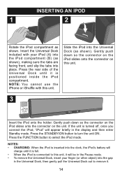
Slide the iPod into the Universal Dock (as shown), making sure the tabs are facing front, and slip the tabs into the gap in the display and then enter Standby mode. If the unit is connected to this unit, it will ...
Slide the iPod into the Universal Dock (as shown), making sure the tabs are facing front, and slip the tabs into the gap in the display and then enter Standby mode. If the unit is connected to this unit, it will ...

User Guide
Page 15
You can operate the iPod using its own controls, as per its owner's manual, or you can use the controls on this unit on by pressing the POWER ON/OFF switch on the main unit to the ON position. CONTINUED ON THE NEXT PAGE 15 OPERATION USING AN iPod WITH THIS UNIT 1 2 With an iPod connected (see previous page), if this unit is not already on, turn this unit to operate the iPod. 3 4 To play/pause the iPod: Press the PLAY/PAUSE (®p) button to start playback on your iPod. If in the display. "iPod" will go out. Press again to select iPod mode; the Standby indicator will ...
You can operate the iPod using its own controls, as per its owner's manual, or you can use the controls on this unit on by pressing the POWER ON/OFF switch on the main unit to the ON position. CONTINUED ON THE NEXT PAGE 15 OPERATION USING AN iPod WITH THIS UNIT 1 2 With an iPod connected (see previous page), if this unit is not already on, turn this unit to operate the iPod. 3 4 To play/pause the iPod: Press the PLAY/PAUSE (®p) button to start playback on your iPod. If in the display. "iPod" will go out. Press again to select iPod mode; the Standby indicator will ...

User Guide
Page 16
the Standby indicator will light. 16 Set the EQ/BASS using the MODE button 3 and the BASS using the VOLUME - 1/+ 2 buttons. OPERATION (CONTINUED) 5 6 1 3 2 To navigate your selection. 7 3 8 4 5 1 2 Adjust the volume using the BASS - 4/+ 5 buttons. Repeatedly press the MENU button to return to browse through the menus. See page 13 for details. Then, press the SELECT button 3 to make your iPod menus: At any time, press the MENU button to go back to the previous screen/menu. To navigate your iPod menus (continued): Use the Navigation UP 1 or DOWN 2 button to ...
the Standby indicator will light. 16 Set the EQ/BASS using the MODE button 3 and the BASS using the VOLUME - 1/+ 2 buttons. OPERATION (CONTINUED) 5 6 1 3 2 To navigate your selection. 7 3 8 4 5 1 2 Adjust the volume using the BASS - 4/+ 5 buttons. Repeatedly press the MENU button to return to browse through the menus. See page 13 for details. Then, press the SELECT button 3 to make your iPod menus: At any time, press the MENU button to go back to the previous screen/menu. To navigate your iPod menus (continued): Use the Navigation UP 1 or DOWN 2 button to ...

User Guide
Page 17
... turned on. The iPod can charge only when the unit is set the TV Out setting to minimum. iPod has incorrect settings selected. SYMPTOM No sound from iPod. Check the connection (see page 12).
... turned on. The iPod can charge only when the unit is set the TV Out setting to minimum. iPod has incorrect settings selected. SYMPTOM No sound from iPod. Check the connection (see page 12).

User Guide
Page 18
...-6993. 18 SPECIFICATIONS Power source AC 120V/60Hz Power consumption 120W Subwoofer impedance 8 Ohm Surround impedance 8 Ohm S/N 60dB Subwoofer power output 50W Left and Right speakers power output 15Wx2 THD (1KHz, 1W 0.5% Frequency response (Subwoofer 40Hz~200Hz 5dB Frequency response (Left and Right channels): ....200Hz~20KHz 5dB L/R separation (1KHz 40dB L/R Balance...
...-6993. 18 SPECIFICATIONS Power source AC 120V/60Hz Power consumption 120W Subwoofer impedance 8 Ohm Surround impedance 8 Ohm S/N 60dB Subwoofer power output 50W Left and Right speakers power output 15Wx2 THD (1KHz, 1W 0.5% Frequency response (Subwoofer 40Hz~200Hz 5dB Frequency response (Left and Right channels): ....200Hz~20KHz 5dB L/R separation (1KHz 40dB L/R Balance...

Service Manual
Page 1
...is connected correctly with of pcb board 6ē Deal with source and speaker. ēRemote control unavailabilityğ aē Check whether battery install correctly. configuration partğ 1ē Explode view dē Check whether the system is too low. MIHTS3202 SERVICE MANUAL Electronic partğ 1ē BOMğ č LIST... a MCUĎ 4ē Transformer specification 5ē Connection chart of familiar faultğ ēNo outputğ aē Check whether the system is set minimum adjust it accordingly. bē Check whether the volume is connected correctly.
...is connected correctly with of pcb board 6ē Deal with source and speaker. ēRemote control unavailabilityğ aē Check whether battery install correctly. configuration partğ 1ē Explode view dē Check whether the system is too low. MIHTS3202 SERVICE MANUAL Electronic partğ 1ē BOMğ č LIST... a MCUĎ 4ē Transformer specification 5ē Connection chart of familiar faultğ ēNo outputğ aē Check whether the system is set minimum adjust it accordingly. bē Check whether the volume is connected correctly.

Service Manual
Page 28
1 2 3 SPEAKER BASS OUT D BASS OUT L OUT CON2 1 2 CON10 1 2 3 4 R OUT C CON9 1 2 3 CON8 MAIN CON12 CON6 CON7 4 CON11 CON1 6 5 4 3 2 1 CON3 3 2 1 6 5 4 3 2 1 5 4 3 2 1 2 1 1 2 5 4 3 2 1 B 5 6 CON401 1 D 2 3 INPUT 4 5 CON402 6 3 2 1 1 4 2 3 3 2 4 1 C CON504 1 2 3 CON502 CON503 4 5 6 IPOD SWITCH ...
1 2 3 SPEAKER BASS OUT D BASS OUT L OUT CON2 1 2 CON10 1 2 3 4 R OUT C CON9 1 2 3 CON8 MAIN CON12 CON6 CON7 4 CON11 CON1 6 5 4 3 2 1 CON3 3 2 1 6 5 4 3 2 1 5 4 3 2 1 2 1 1 2 5 4 3 2 1 B 5 6 CON401 1 D 2 3 INPUT 4 5 CON402 6 3 2 1 1 4 2 3 3 2 4 1 C CON504 1 2 3 CON502 CON503 4 5 6 IPOD SWITCH ...