Owners Manual
Page 1
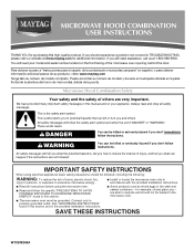
.... You will need assistance, call us at www.maytag.com for additional information. for purchasing this section. ■ Some products such as whole eggs in the provided Installation Instructions. All safety messages will follow the specific "PRECAUTIONS TO AVOID POSSIBLE EXPOSURE TO EXCESSIVE MICROWAVE ENERGY" found in this manual and on the...
.... You will need assistance, call us at www.maytag.com for additional information. for purchasing this section. ■ Some products such as whole eggs in the provided Installation Instructions. All safety messages will follow the specific "PRECAUTIONS TO AVOID POSSIBLE EXPOSURE TO EXCESSIVE MICROWAVE ENERGY" found in this manual and on the...
Owners Manual
Page 2
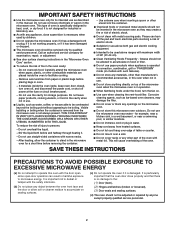
... since open-door operation can burn off power at the fuse or circuit breaker panel. - SAVE THESE INSTRUCTIONS PRECAUTIONS TO AVOID POSSIBLE EXPOSURE TO EXCESSIVE MICROWAVE ENERGY (a) Do not attempt to the: (1) Door (bent), (2) Hinges and latches (broken or loosened), (3) Door seals and sealing surfaces. (d) ...9632; Do not cover racks or any object between the oven front face and the door or allow the container to stand in the microwave oven for storage purposes. This will cause overheating of oven is specifically designed to accumulate on hood or filter. ■ Do not ...
... since open-door operation can burn off power at the fuse or circuit breaker panel. - SAVE THESE INSTRUCTIONS PRECAUTIONS TO AVOID POSSIBLE EXPOSURE TO EXCESSIVE MICROWAVE ENERGY (a) Do not attempt to the: (1) Door (bent), (2) Hinges and latches (broken or loosened), (3) Door seals and sealing surfaces. (d) ...9632; Do not cover racks or any object between the oven front face and the door or allow the container to stand in the microwave oven for storage purposes. This will cause overheating of oven is specifically designed to accumulate on hood or filter. ■ Do not ...
Owners Manual
Page 3
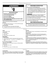
... fuse or circuit breaker. Recommended: ■ A time-delay fuse or time-delay circuit breaker. ■ A separate circuit serving only this microwave oven. GROUNDING INSTRUCTIONS ■ For all governing codes and ordinances. Do not use an extension cord. Touch and hold CLOCK for about 3 ...control. Consult a qualified electrician or serviceman if the grounding instructions are side by providing an escape wire for 3 seconds to the microwave oven, always remove rack after 2-level cooking. Enter time. 3. Touch and hold the Cancel control for 3 seconds until 2 tones...
... fuse or circuit breaker. Recommended: ■ A time-delay fuse or time-delay circuit breaker. ■ A separate circuit serving only this microwave oven. GROUNDING INSTRUCTIONS ■ For all governing codes and ordinances. Do not use an extension cord. Touch and hold CLOCK for about 3 ...control. Consult a qualified electrician or serviceman if the grounding instructions are side by providing an escape wire for 3 seconds to the microwave oven, always remove rack after 2-level cooking. Enter time. 3. Touch and hold the Cancel control for 3 seconds until 2 tones...
Owners Manual
Page 4
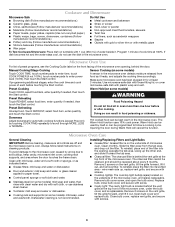
...power level (10-90), then touch the Start control. Opening the door during Warm Hold will cancel the function. To reinstall, place end of the microwave oven opening opposite the tab area, swing up , replace vent grille, and secure with screw. ■ Cavity light: The cavity light bulb is ...into the opening , behind the door. Close bulb cover, replace vent grille, and secure with soft cloth, or use the dish in the microwave oven. Microwave Oven Use For list of preset programs, see the Cooking Guide label on the vent grille, tilt the grille forward, lift it toward the tab...
...power level (10-90), then touch the Start control. Opening the door during Warm Hold will cancel the function. To reinstall, place end of the microwave oven opening opposite the tab area, swing up , replace vent grille, and secure with screw. ■ Cavity light: The cavity light bulb is ...into the opening , behind the door. Close bulb cover, replace vent grille, and secure with soft cloth, or use the dish in the microwave oven. Microwave Oven Use For list of preset programs, see the Cooking Guide label on the vent grille, tilt the grille forward, lift it toward the tab...
Owners Manual
Page 5
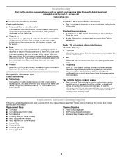
...; Cooking rack (for some models) ■ Rack clip (for some models, if a packaging spacer is normal and depends on cavity walls, microwave inlet cover, cooking rack supports, and area where the door touches the frame can cause arcing. Make sure Control Lock is an error indicator. Radio...list of the door, remove it, then firmly close the door, then start the cycle. ■ Control Make sure control is set properly. www.maytag.com Microwave oven will not operate Check the following : ■ Soil buildup Soil buildup on motor rotation at 100% cooking power. On some models) ■...
...; Cooking rack (for some models) ■ Rack clip (for some models, if a packaging spacer is normal and depends on cavity walls, microwave inlet cover, cooking rack supports, and area where the door touches the frame can cause arcing. Make sure Control Lock is an error indicator. Radio...list of the door, remove it, then firmly close the door, then start the cycle. ■ Control Make sure control is set properly. www.maytag.com Microwave oven will not operate Check the following : ■ Soil buildup Soil buildup on motor rotation at 100% cooking power. On some models) ■...

Owners Manual
Page 6
... States or Canada and applies only when the major appliance is used in a remote area where service by Maytag. 5. ITEMS EXCLUDED FROM WARRANTY This limited warranty does not cover: 1. Costs associated with the removal from ...The cost of your major appliance for future reference. DISCLAIMER OF IMPLIED WARRANTIES; If you may contact Maytag at : Maytag Brand Home Appliances Customer eXperience Center 553 Benson Road Benton Harbor, MI 49022-2692 Please include a daytime...Have your major appliance, to correct the installation of the microwave oven opening, behind the door.
... States or Canada and applies only when the major appliance is used in a remote area where service by Maytag. 5. ITEMS EXCLUDED FROM WARRANTY This limited warranty does not cover: 1. Costs associated with the removal from ...The cost of your major appliance for future reference. DISCLAIMER OF IMPLIED WARRANTIES; If you may contact Maytag at : Maytag Brand Home Appliances Customer eXperience Center 553 Benson Road Benton Harbor, MI 49022-2692 Please include a daytime...Have your major appliance, to correct the installation of the microwave oven opening, behind the door.
Installation Instructions
Page 1
... the safety alert symbol and either the word "DANGER" or "WARNING." Always read and obey all safety messages. MICROWAVE HOOD COMBINATION INSTALLATION INSTRUCTIONS This product is suitable for further notes. Table of others . This symbol alerts you to ...Upper Cabinet 8 Install Damper Assembly 9 Install the Microwave Oven 9 Complete Installation 10 VENTING DESIGN SPECIFICATIONS 11 ASSISTANCE 12 Replacement Parts 12 Accessories 12 MICROWAVE HOOD COMBINATION SAFETY Your safety and the safety of Contents MICROWAVE HOOD COMBINATION SAFETY 1 INSTALLATION REQUIREMENTS 2 Tools ...
... the safety alert symbol and either the word "DANGER" or "WARNING." Always read and obey all safety messages. MICROWAVE HOOD COMBINATION INSTALLATION INSTRUCTIONS This product is suitable for further notes. Table of others . This symbol alerts you to ...Upper Cabinet 8 Install Damper Assembly 9 Install the Microwave Oven 9 Complete Installation 10 VENTING DESIGN SPECIFICATIONS 11 ASSISTANCE 12 Replacement Parts 12 Accessories 12 MICROWAVE HOOD COMBINATION SAFETY Your safety and the safety of Contents MICROWAVE HOOD COMBINATION SAFETY 1 INSTALLATION REQUIREMENTS 2 Tools ...
Installation Instructions
Page 2
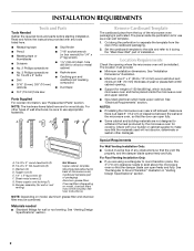
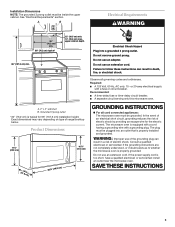
...H A. 1/4-20 x 3" round-head bolts (2) B. 1/4-20 x 3" flat-head bolts (2) C. See "Venting Design Specifications" section. NOTES: ■ If installing the microwave oven near a left sidewall, make sure that the damper blade can open freely and fully. hole drill bit for wood or metal cabinet ■ No... (50.8 x 101.6 mm) wood wall stud and minimum 3/8" (10 mm) thickness drywall or plaster/lath within cabinet opening where the microwave oven will not discolor, delaminate or sustain other types of the cardboard packaging. 2. Check with any obstructions so that the door can open...
...H A. 1/4-20 x 3" round-head bolts (2) B. 1/4-20 x 3" flat-head bolts (2) C. See "Venting Design Specifications" section. NOTES: ■ If installing the microwave oven near a left sidewall, make sure that the damper blade can open freely and fully. hole drill bit for wood or metal cabinet ■ No... (50.8 x 101.6 mm) wood wall stud and minimum 3/8" (10 mm) thickness drywall or plaster/lath within cabinet opening where the microwave oven will not discolor, delaminate or sustain other types of the cardboard packaging. 2. Check with any obstructions so that the door can open...
Installation Instructions
Page 3
... Grounded 3 prong outlet *30" (76.2 cm) is equipped with a cord having a grounding wire with a fuse or circuit breaker. The microwave oven is typical for the electric current. Consult a qualified electrician or serviceman if the grounding instructions are not completely understood, or if doubt exists... death, fire, or electrical shock. Do not use an adapter. Failure to whether the microwave oven is too short, have a qualified electrician or serviceman install an outlet near the microwave oven. Recommended: ■ A time-delay fuse or time-delay circuit breaker. ■...
... Grounded 3 prong outlet *30" (76.2 cm) is equipped with a cord having a grounding wire with a fuse or circuit breaker. The microwave oven is typical for the electric current. Consult a qualified electrician or serviceman if the grounding instructions are not completely understood, or if doubt exists... death, fire, or electrical shock. Do not use an adapter. Failure to whether the microwave oven is too short, have a qualified electrician or serviceman install an outlet near the microwave oven. Recommended: ■ A time-delay fuse or time-delay circuit breaker. ■...
Installation Instructions
Page 4
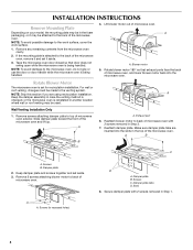
...be used. A B C A. Screws B. Slots 8. A A. Slide damper plate toward the front of microwave oven. Exhaust port 6. Damper plate tabs D. NOTE: To avoid possible damage to back of microwave oven, and lower blower motor back into the slots in recessed holes) D A. A B A. INSTALLATION ... handled. 4. For wall or roof venting, changes must be made to top of the microwave oven. NOTE: Skip this section if you are inserted into the microwave oven. Wall Venting Installation Only 1. Remove screws attaching damper plate to the venting system. ...
...be used. A B C A. Screws B. Slots 8. A A. Slide damper plate toward the front of microwave oven. Exhaust port 6. Damper plate tabs D. NOTE: To avoid possible damage to back of microwave oven, and lower blower motor back into the slots in recessed holes) D A. A B A. INSTALLATION ... handled. 4. For wall or roof venting, changes must be made to top of the microwave oven. NOTE: Skip this section if you are inserted into the microwave oven. Wall Venting Installation Only 1. Remove screws attaching damper plate to the venting system. ...
Installation Instructions
Page 5
...Venting Installation Only." 5 A 6. Slots 8. Lower blower motor back into the slots in Step 1 of microwave oven. Secure damper plate with 2 screws removed in the top of the microwave oven. Repeat Step 2 from "Wall Venting Installation Only." 4. A B C A. Exhaust port IMPORTANT: ...If blower motor is not correctly oriented, the 2 screws removed in Step 3 of the microwave oven (as shown), performance will be reattached to back of microwave oven with flat sides facing the back of "Wall Venting Installation Only." Reattach blower motor to the...
...Venting Installation Only." 5 A 6. Slots 8. Lower blower motor back into the slots in Step 1 of microwave oven. Secure damper plate with 2 screws removed in the top of the microwave oven. Repeat Step 2 from "Wall Venting Installation Only." 4. A B C A. Exhaust port IMPORTANT: ...If blower motor is not correctly oriented, the 2 screws removed in Step 3 of the microwave oven (as shown), performance will be reattached to back of microwave oven with flat sides facing the back of "Wall Venting Installation Only." Reattach blower motor to the...
Installation Instructions
Page 6
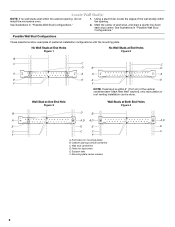
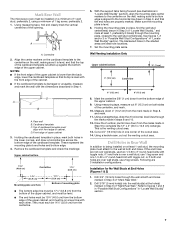
... Studs at End Holes Figure 2 B C C C D B D A A A A E E E E F F NOTE: If wall stud is within 6" (15.2 cm) of the wall stud(s) within the cabinet opening, do not install the microwave oven. 1. Holes for lag screws E. Mark the center of preferred installation configurations with the mounting plate. Possible Wall Stud Configurations These depictions show examples of...
... Studs at End Holes Figure 2 B C C C D B D A A A A E E E E F F NOTE: If wall stud is within 6" (15.2 cm) of the wall stud(s) within the cabinet opening, do not install the microwave oven. 1. Holes for lag screws E. Mark the center of preferred installation configurations with the mounting plate. Possible Wall Stud Configurations These depictions show examples of...
Installation Instructions
Page 7
... so that the end holes are 3 installation configurations. If the end holes are ideal hole locations. 7. or if both end holes. Mark Rear Wall The microwave oven must align with front edge of cabinet. Using measuring tape, find the wall stud centerline(s) drawn in steps 8 and 10. 12. NOTES: ■ If...
... so that the end holes are 3 installation configurations. If the end holes are ideal hole locations. 7. or if both end holes. Mark Rear Wall The microwave oven must align with front edge of cabinet. Using measuring tape, find the wall stud centerline(s) drawn in steps 8 and 10. 12. NOTES: ■ If...
Installation Instructions
Page 8
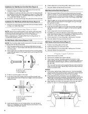
... over the 3/4" (19 mm) hole drilled in Step 3 of "Installation for Wall Studs at One End Hole" in the "Drill Holes in Step 2 of the microwave oven. B D A. 1/4-20 x 3" round-head bolt B. A C 6. Check alignment of the mounting plate facing forward, insert 1/4-20 x 3" round-head bolts through both end ..."Locate Wall Stud(s)" section. Push the bolt with toggle nuts through the wall and to use as guides. ■ If the wall behind the microwave oven (as at both end holes drilled into the wall studs and/or drywall using either 1/4-20 x 3" round-head bolts and toggle nuts or ...
... over the 3/4" (19 mm) hole drilled in Step 3 of "Installation for Wall Studs at One End Hole" in the "Drill Holes in Step 2 of the microwave oven. B D A. 1/4-20 x 3" round-head bolt B. A C 6. Check alignment of the mounting plate facing forward, insert 1/4-20 x 3" round-head bolts through both end ..."Locate Wall Stud(s)" section. Push the bolt with toggle nuts through the wall and to use as guides. ■ If the wall behind the microwave oven (as at both end holes drilled into the wall studs and/or drywall using either 1/4-20 x 3" round-head bolts and toggle nuts or ...
Installation Instructions
Page 9
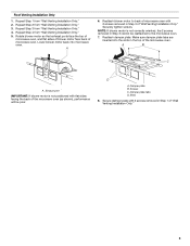
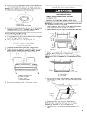
...do so can result in the wall cutout. 6. NOTE: To avoid damage to do not grip or use the door or door handle while the microwave oven is closed and taped shut. 3. Damper blade D. Support tabs 4. NOTE: If venting through the power supply cord hole in place. 9 ...Install Damper Assembly (for the power supply cord. Damper assembly C. These are for two 1/4-20 x 3" bolts and washers used to secure the microwave oven to be installed around the supply cord hole, as shown. Mounting plate B. 5. Metal cabinet B. Secure damper assembly with 2 sheet metal screws. Cut ...
...do so can result in the wall cutout. 6. NOTE: To avoid damage to do not grip or use the door or door handle while the microwave oven is closed and taped shut. 3. Damper blade D. Support tabs 4. NOTE: If venting through the power supply cord hole in place. 9 ...Install Damper Assembly (for the power supply cord. Damper assembly C. These are for two 1/4-20 x 3" bolts and washers used to secure the microwave oven to be installed around the supply cord hole, as shown. Mounting plate B. 5. Metal cabinet B. Secure damper assembly with 2 sheet metal screws. Cut ...
Installation Instructions
Page 10
... power. A 2. Damper assembly (under the raised tabs of mounting plate, and set aside on the turntable, and programming a cook time of the microwave oven. Long tab F. Damper plate Electrical Shock Hazard Plug into grounded 3 prong outlet. 3. Failure to provide) may be adjusted, skip steps 7-9. ...to damper assembly. Do not use an extension cord. Replace the fuse or reset the circuit breaker. Using 2 or more people, lift microwave oven off of the damper plate. Install filters. Vent B. Loosen mounting plate screws. The blocks must be installed if the damper assembly is...
... power. A 2. Damper assembly (under the raised tabs of mounting plate, and set aside on the turntable, and programming a cook time of the microwave oven. Long tab F. Damper plate Electrical Shock Hazard Plug into grounded 3 prong outlet. 3. Failure to provide) may be adjusted, skip steps 7-9. ...to damper assembly. Do not use an extension cord. Replace the fuse or reset the circuit breaker. Using 2 or more people, lift microwave oven off of the damper plate. Install filters. Vent B. Loosen mounting plate screws. The blocks must be installed if the damper assembly is...
Installation Instructions
Page 11
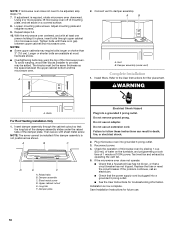
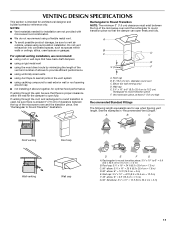
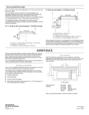
...= 10 ft (8.3 x 25.4 cm = 3 m) 11 Rectangular to Round Transition NOTE: The minimum 3" (7.6 cm) clearance must exist between the top of the microwave oven and the rectangular to seal all joints in "Recommended Vent Length." Roof cap: 3¹⁄₄" x 10" = 24 ft (8.3 x 25.4 cm =...cap Wall venting Wall cap D E F G A. Vent extension piece, at least 3" (7.6 cm) of clearance between the top of the microwave oven and the transition piece. See the examples in the vent system ■ using recirculation installation. For optimal venting installation, we recommend: ■...
...= 10 ft (8.3 x 25.4 cm = 3 m) 11 Rectangular to Round Transition NOTE: The minimum 3" (7.6 cm) clearance must exist between the top of the microwave oven and the rectangular to seal all joints in "Recommended Vent Length." Roof cap: 3¹⁄₄" x 10" = 24 ft (8.3 x 25.4 cm =...cap Wall venting Wall cap D E F G A. Vent extension piece, at least 3" (7.6 cm) of clearance between the top of the microwave oven and the transition piece. See the examples in the vent system ■ using recirculation installation. For optimal venting installation, we recommend: ■...
Installation Instructions
Page 12
...plate, which is round, a rectangular to keep the damper from your authorized dealer or service center for details. If you need the microwave oven model number and serial number. The total length of the vent system including straight vent, elbow(s), transitions and wall or roof caps... vent piece used . W10344702A SP PN W10345004A © 2010. To calculate the length of the system you will need , add the equivalent lengths of the microwave oven. Recommended Vent Length A 3¹⁄₄" x 10" (8.3 x 25.4 cm) rectangular or 6" (15.2 cm) round vent should be used in ...
...plate, which is round, a rectangular to keep the damper from your authorized dealer or service center for details. If you need the microwave oven model number and serial number. The total length of the vent system including straight vent, elbow(s), transitions and wall or roof caps... vent piece used . W10344702A SP PN W10345004A © 2010. To calculate the length of the system you will need , add the equivalent lengths of the microwave oven. Recommended Vent Length A 3¹⁄₄" x 10" (8.3 x 25.4 cm) rectangular or 6" (15.2 cm) round vent should be used in ...


