
Installation Instructions
Page 1
... and either the word "DANGER" or "WARNING." Table of Contents MICROWAVE HOOD COMBINATION SAFETY 1 INSTALLATION REQUIREMENTS 2 Tools and Parts 2 Remove Cardboard Template 2 Location Requirements 2 Product Dimensions 3 Electrical Requirements 3 INSTALLATION INSTRUCTIONS 4 Remove Mounting Plate 4 Rotate Blower Motor 4 Locate Wall Stud(s 6 Mark Rear Wall 7 Drill Holes in Rear Wall 7 Attach Mounting Plate to...
... and either the word "DANGER" or "WARNING." Table of Contents MICROWAVE HOOD COMBINATION SAFETY 1 INSTALLATION REQUIREMENTS 2 Tools and Parts 2 Remove Cardboard Template 2 Location Requirements 2 Product Dimensions 3 Electrical Requirements 3 INSTALLATION INSTRUCTIONS 4 Remove Mounting Plate 4 Rotate Blower Motor 4 Locate Wall Stud(s 6 Mark Rear Wall 7 Drill Holes in Rear Wall 7 Attach Mounting Plate to...

Installation Instructions
Page 2
...the damper blade opens freely and fully. Special Requirements For Wall Venting Installation Only: ■ Cutout must provide: ■ Minimum installation dimensions. For Roof Venting Installation Only: ■ If you are for weight of the microwave oven packaging is perforated. Toggle nuts (2) E....2" lag screws ■ 1½" (3.8 cm) diam. See User Instructions.) NOTE: Depending on model, charcoal filters may be installed. See "Installation Dimensions" illustration. ■ Minimum one 2" x 4" (50.8 x 101.6 mm) wood wall stud and minimum 3/8" (10 mm) thickness drywall or ...
...the damper blade opens freely and fully. Special Requirements For Wall Venting Installation Only: ■ Cutout must provide: ■ Minimum installation dimensions. For Roof Venting Installation Only: ■ If you are for weight of the microwave oven packaging is perforated. Toggle nuts (2) E....2" lag screws ■ 1½" (3.8 cm) diam. See User Instructions.) NOTE: Depending on model, charcoal filters may be installed. See "Installation Dimensions" illustration. ■ Minimum one 2" x 4" (50.8 x 101.6 mm) wood wall stud and minimum 3/8" (10 mm) thickness drywall or ...

Installation Instructions
Page 3
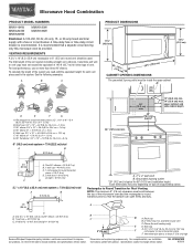
Installation Dimensions NOTE: The grounded 3 prong outlet must be grounded. A B Electrical Requirements WARNING 66" (167.6 cm) min. 30" (76.2 cm) min. 30" (76.2 cm) typical* 12" (30.5 ..." (167.6 cm) installation height. Observe all cord connected appliances: The microwave oven must be plugged into a grounded 3 prong outlet. Exact dimensions may vary depending on type of range/cooktop below. Product Dimensions 17¹⁄₄" (43.8 cm) 16¹⁄₄" (41.3 cm) (411.06¹c⁄₈m") 29⁷⁄...
Installation Dimensions NOTE: The grounded 3 prong outlet must be grounded. A B Electrical Requirements WARNING 66" (167.6 cm) min. 30" (76.2 cm) min. 30" (76.2 cm) typical* 12" (30.5 ..." (167.6 cm) installation height. Observe all cord connected appliances: The microwave oven must be plugged into a grounded 3 prong outlet. Exact dimensions may vary depending on type of range/cooktop below. Product Dimensions 17¹⁄₄" (43.8 cm) 16¹⁄₄" (41.3 cm) (411.06¹c⁄₈m") 29⁷⁄...

Installation Instructions
Page 7
.... Drill 3/16" (5 mm) hole(s) into the wall stud(s) at both end holes are not over a wall stud, use two 1/4-20 x 3" round-head bolts with the dimensions described in the lower corners, and draw a horizontal line across the bottom edge of "Locate Wall Stud(s)," and mark at least 1, preferably 2 hole(s) through the...
.... Drill 3/16" (5 mm) hole(s) into the wall stud(s) at both end holes are not over a wall stud, use two 1/4-20 x 3" round-head bolts with the dimensions described in the lower corners, and draw a horizontal line across the bottom edge of "Locate Wall Stud(s)," and mark at least 1, preferably 2 hole(s) through the...

Installation Instructions
Page 8
... into the remaining end hole. 6. Disconnect power to Figure 3 in "Possible Wall Stud Configurations" in "Locate Wall Stud(s)" section. Make sure the 10" (25.4 cm) dimension from upper cabinet. 3.
... into the remaining end hole. 6. Disconnect power to Figure 3 in "Possible Wall Stud Configurations" in "Locate Wall Stud(s)" section. Make sure the 10" (25.4 cm) dimension from upper cabinet. 3.
Dimension Guide
Page 1
...¹⁄₄" (43.8 cm) (411.06¹c⁄₈m") 29⁷⁄₈" (76.0 cm) CABINET OPENING DIMENSIONS The grounded 3-prong outlet must be used in the system. Wall cap: 3 " x 10" = 40 ft (8.3 x 25.4 cm = 12.2 m) F. 45° elbow: 6" = ... 10" = 24 ft (8.3 x 25.4 cm = 7.3 m) C. 90° elbow: 3 " x 10" = 25 ft (8.3 x 25.4 cm = 7.6 m) D. 90° elbow: 6" = 10 ft (15.2 cm = 3 m) E. Exact dimensions may vary depending on type of vent. One 3 " x 10" (8.3 x 25.4 cm) 90° elbow = 25 ft (7.6 m) B. 1 wall cap = 40 ft (12.2 m) C. 2 ft (0.6 m) + 6 ft (1.8 m) straight = ...
...¹⁄₄" (43.8 cm) (411.06¹c⁄₈m") 29⁷⁄₈" (76.0 cm) CABINET OPENING DIMENSIONS The grounded 3-prong outlet must be used in the system. Wall cap: 3 " x 10" = 40 ft (8.3 x 25.4 cm = 12.2 m) F. 45° elbow: 6" = ... 10" = 24 ft (8.3 x 25.4 cm = 7.3 m) C. 90° elbow: 3 " x 10" = 25 ft (8.3 x 25.4 cm = 7.6 m) D. 90° elbow: 6" = 10 ft (15.2 cm = 3 m) E. Exact dimensions may vary depending on type of vent. One 3 " x 10" (8.3 x 25.4 cm) 90° elbow = 25 ft (7.6 m) B. 1 wall cap = 40 ft (12.2 m) C. 2 ft (0.6 m) + 6 ft (1.8 m) straight = ...
