
User Guide
Page 2
... If storage is provided,it is installed near an appliance. RECOGNIZESAFETY SYMBOLS, WORDS, LABELS A.,,,,,,,-,o ] WARNINGH- Followthegas supplier's instructions. . To ensure properand safe operation: Appliancemustbeproperlyinstalledandgroundedby a qualifiedtechnician.Do notattemptto adjust, repair,service,or replaceanypartof yourappliance unless it shouldbe ...limited to shut it off in your gas supplier from parts of this or any phone in an emergency. Always disconnect power to a lighted surfaceburner. iF YOU SMELL GAS: ' Do not try to a qualifiedservicer. ...
... If storage is provided,it is installed near an appliance. RECOGNIZESAFETY SYMBOLS, WORDS, LABELS A.,,,,,,,-,o ] WARNINGH- Followthegas supplier's instructions. . To ensure properand safe operation: Appliancemustbeproperlyinstalledandgroundedby a qualifiedtechnician.Do notattemptto adjust, repair,service,or replaceanypartof yourappliance unless it shouldbe ...limited to shut it off in your gas supplier from parts of this or any phone in an emergency. Always disconnect power to a lighted surfaceburner. iF YOU SMELL GAS: ' Do not try to a qualifiedservicer. ...

User Guide
Page 8
... replace appliance light bulbs, air filters or water filters. Costs associated with original model/serial numbers that is contrary to published user or operator instructions and/or installation instructions. 4. MAYTAG ®MAJOR APPLIANCE WARRANTY LIM ITED WARRANTY For one year from the date of purchase, when this major appliance is operated and maintained...
... replace appliance light bulbs, air filters or water filters. Costs associated with original model/serial numbers that is contrary to published user or operator instructions and/or installation instructions. 4. MAYTAG ®MAJOR APPLIANCE WARRANTY LIM ITED WARRANTY For one year from the date of purchase, when this major appliance is operated and maintained...

Installation Manual
Page 1
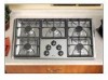
... 87.6 + 0.2 B 19 15/16 + 1/16 50.6 + 0.2 C 21/8 + 1/16 5.4 + 0.2 D 5 1/4 + 1/16 13.3 + 0.2 E 36 + 1/16 91.4 + 0.2 F 21 + 1/16 53.3 + 0.2 G 313/16 + 1/16 9.7 + 0.2 H 15 1/4 + 1/16 38.7 + 0.2 CUTOUT DIMENSIONS C G H I ,o SEALEDGAS COOKTOPS Models: MGC5430 & MGC5536 IMPORTANT: Dimensions Shown in Both Inches and Centimeters. I - NOTICE TO INSTALLER: Leave these instructions for this appliance for use with the appliance. Do not attempt...
... 87.6 + 0.2 B 19 15/16 + 1/16 50.6 + 0.2 C 21/8 + 1/16 5.4 + 0.2 D 5 1/4 + 1/16 13.3 + 0.2 E 36 + 1/16 91.4 + 0.2 F 21 + 1/16 53.3 + 0.2 G 313/16 + 1/16 9.7 + 0.2 H 15 1/4 + 1/16 38.7 + 0.2 CUTOUT DIMENSIONS C G H I ,o SEALEDGAS COOKTOPS Models: MGC5430 & MGC5536 IMPORTANT: Dimensions Shown in Both Inches and Centimeters. I - NOTICE TO INSTALLER: Leave these instructions for this appliance for use with the appliance. Do not attempt...
Installation Manual
Page 2
...use of cabinets above cooktop for gas leaks with an open flames. Installing Cabinetry Over Maytag Cooktop A = 30" (76.2 cm) minimum vertical clearance between the edge of the appliance and combustible construction extending from the cooking surface to 18" (45.72 cm) above cooktop. WARNING THIS PRODUCTSHOULDNOT ...prepared according to not less than 24 inches (60.96 cm) by A protecting the underside of cabinets installed above the cooking surface is the fuel of choice, follow the conversion to LP procedure found in the installation instructions. [] Test all exposed edges of ...
...use of cabinets above cooktop for gas leaks with an open flames. Installing Cabinetry Over Maytag Cooktop A = 30" (76.2 cm) minimum vertical clearance between the edge of the appliance and combustible construction extending from the cooking surface to 18" (45.72 cm) above cooktop. WARNING THIS PRODUCTSHOULDNOT ...prepared according to not less than 24 inches (60.96 cm) by A protecting the underside of cabinets installed above the cooking surface is the fuel of choice, follow the conversion to LP procedure found in the installation instructions. [] Test all exposed edges of ...

Installation Manual
Page 3
... use with LP gas (propane or butane), 10 inches water column. Installation Of Appliance The installation of LP gas. A "T" handle type manual gas valve must be made by a qualified service technician before attempting to operate the cooktop on natural gas or, if converted for use an approved pipe joint compound resistant to these instructions as described on...
... use with LP gas (propane or butane), 10 inches water column. Installation Of Appliance The installation of LP gas. A "T" handle type manual gas valve must be made by a qualified service technician before attempting to operate the cooktop on natural gas or, if converted for use an approved pipe joint compound resistant to these instructions as described on...

Installation Manual
Page 4
... OTHER APPLIANCE IS TO BE INSTALLED BELOW THIS COOKTOP Join the appliance pressure regulator supplied with the manufacturer's instructions. Always use in the gas line ahead of gas flow. Make the gas connection to 30 ft-lbs of turning on the supply line gas shut off valve and the cooktop. APPRPESLSIAUNRCEE REGULATOR ALL SUPPLY SIDE PIPE JOINTS...
... OTHER APPLIANCE IS TO BE INSTALLED BELOW THIS COOKTOP Join the appliance pressure regulator supplied with the manufacturer's instructions. Always use in the gas line ahead of gas flow. Make the gas connection to 30 ft-lbs of turning on the supply line gas shut off valve and the cooktop. APPRPESLSIAUNRCEE REGULATOR ALL SUPPLY SIDE PIPE JOINTS...

Installation Manual
Page 6
...all joints and fittings in the gas connection between 11 and 14 inches of the appliance shall be isolated from the gas supply piping system during installation. ILLUSTRATIVE ALTERNATIVE PIPING Apply a non-corrosive leak detection fluid to the instructions given. Check for leaks. If ...piping (either gas supply or the appliance manifold) so as its gas supply. Pipe (Stationary Supply Pipe) NO APPLIANCE MOUNTED BELOW THIS COOKTOP WALL OVEN MOUNTED IN CABINETRY BELOW THIS COOKTOP FIGURE5 Regulator,Supplied -,ql-- (Opbpsliearnvece Pressure directionality of the gas supply piping system...
...all joints and fittings in the gas connection between 11 and 14 inches of the appliance shall be isolated from the gas supply piping system during installation. ILLUSTRATIVE ALTERNATIVE PIPING Apply a non-corrosive leak detection fluid to the instructions given. Check for leaks. If ...piping (either gas supply or the appliance manifold) so as its gas supply. Pipe (Stationary Supply Pipe) NO APPLIANCE MOUNTED BELOW THIS COOKTOP WALL OVEN MOUNTED IN CABINETRY BELOW THIS COOKTOP FIGURE5 Regulator,Supplied -,ql-- (Opbpsliearnvece Pressure directionality of the gas supply piping system...

Installation Manual
Page 7
... of the burner box, when viewed from this appliance and the counter units outlet is in the dividing wall between the cabinets. WARNING Electrical Grounding Instructions This appliance is equipped with a grounded type power cord. DISCONSUPPLY BEFORE 3 13116" 9.7 cm _iiiiiiiiiiiiiiiiiiiiiiiiiiiiiiiiiiiiiiiiiiiiiiiiiiiiiiiiiiiiiiiiiiiiiiiiiiiiiiiiiiiiiiiiiiiiiiiiiiiiiiiiiiiiiiii _i!i!iii!!!!!iiiii!_i_i_i_!!!!i_i_!!!!!i!!iii!ii!!iii!iiiiiiiiiiiiiiiiiiiiiiiiiiiiiiiii!!!!_ Ii!!!!!!!!!i!iiiiiiiiiiiiiiiiiiiiiiiiiiiiiiiiiiiiiiiiiiiiiiiiiiiiiiiiiii...
... of the burner box, when viewed from this appliance and the counter units outlet is in the dividing wall between the cabinets. WARNING Electrical Grounding Instructions This appliance is equipped with a grounded type power cord. DISCONSUPPLY BEFORE 3 13116" 9.7 cm _iiiiiiiiiiiiiiiiiiiiiiiiiiiiiiiiiiiiiiiiiiiiiiiiiiiiiiiiiiiiiiiiiiiiiiiiiiiiiiiiiiiiiiiiiiiiiiiiiiiiiiiiiiiiiiii _i!i!iii!!!!!iiiii!_i_i_i_!!!!i_i_!!!!!i!!iii!ii!!iii!iiiiiiiiiiiiiiiiiiiiiiiiiiiiiiiii!!!!_ Ii!!!!!!!!!i!iiiiiiiiiiiiiiiiiiiiiiiiiiiiiiiiiiiiiiiiiiiiiiiiiiiiiiiiiii...

Installation Manual
Page 8
... burner. Converting Appliance For Use With LP Gas WARNING Propane conversion is to be performed by a MAYTAG AUTHORIZED SERVICER (or other qualified agency) in accordance with the manufacturer's instructions and all codes and requirements of 15 to 20 inch-lbs. This appliance was adjusted at the ...factory for future use with natural gas. REPLACE ALL ORIFICE SPUDS Step ...
... burner. Converting Appliance For Use With LP Gas WARNING Propane conversion is to be performed by a MAYTAG AUTHORIZED SERVICER (or other qualified agency) in accordance with the manufacturer's instructions and all codes and requirements of 15 to 20 inch-lbs. This appliance was adjusted at the ...factory for future use with natural gas. REPLACE ALL ORIFICE SPUDS Step ...

Installation Manual
Page 10
...grommets. 4. Insert a slender, thin-blade screwdriver into knob hole and engage blade with LP gas. Perform Steps 1 and 2 on page 8 to complete the installation of appliance regulator and follow the instructions in either figure 3, 4 or 5 (pages 4, 5 & 6). Save the orifices removed from... the spuds and note the correct burner location for use with slot in their correct locations. 5. REPLACE ALL ORIFICE SPUDS. 1. Installation Of Natural Gas Orifice Spuds 5 BURNER MODEL (36" WIDE) 1.42 1.55_-_ 1.07 © © © @ 1,55 _] 1,85 FIGURE 15 4. Complete Steps 5, 6 and 7 ...
...grommets. 4. Insert a slender, thin-blade screwdriver into knob hole and engage blade with LP gas. Perform Steps 1 and 2 on page 8 to complete the installation of appliance regulator and follow the instructions in either figure 3, 4 or 5 (pages 4, 5 & 6). Save the orifices removed from... the spuds and note the correct burner location for use with slot in their correct locations. 5. REPLACE ALL ORIFICE SPUDS. 1. Installation Of Natural Gas Orifice Spuds 5 BURNER MODEL (36" WIDE) 1.42 1.55_-_ 1.07 © © © @ 1,55 _] 1,85 FIGURE 15 4. Complete Steps 5, 6 and 7 ...

Installation Manual
Page 12
...See figure 19). 5. See figures 18 and 19. Remove hold down brackets may be added to the front and/or rear. Position the cooktop in the cutout opening. Open cabinet doors and locate screw holes at right and left and one on the left side of unit bottom. .... Thread the long hold-down screws into the hold -down brackets. The servicer MUST follow installation instructions provided with the gas appliance connector and the warning label attached to the counter top. If gas line has been disconnected, check for servicing: 1. Utilize the hold -down brackets, one on the...
...See figure 19). 5. See figures 18 and 19. Remove hold down brackets may be added to the front and/or rear. Position the cooktop in the cutout opening. Open cabinet doors and locate screw holes at right and left and one on the left side of unit bottom. .... Thread the long hold-down screws into the hold -down brackets. The servicer MUST follow installation instructions provided with the gas appliance connector and the warning label attached to the counter top. If gas line has been disconnected, check for servicing: 1. Utilize the hold -down brackets, one on the...