
Service Manual
Page 1
Service This manual is not limited to the following: Amana AFI2237AE* AFI2538AE* AFD25BCZX* AFD25WBZX* Maytag MFI2067AE* MFI2266AE* MFI2568AE* 16026312 February 2006 Ice and Water Bottom Mount Refrigerators This Base Manual covers general information Refer to be used by an unqualified person. Maytag does not assume any responsibility for property damage or personal injury for information on specific models This manual includes, but is to individual Technical Sheet for improper service procedures done by qualified appliance technicians only.
Service This manual is not limited to the following: Amana AFI2237AE* AFI2538AE* AFD25BCZX* AFD25WBZX* Maytag MFI2067AE* MFI2266AE* MFI2568AE* 16026312 February 2006 Ice and Water Bottom Mount Refrigerators This Base Manual covers general information Refer to be used by an unqualified person. Maytag does not assume any responsibility for property damage or personal injury for information on specific models This manual includes, but is to individual Technical Sheet for improper service procedures done by qualified appliance technicians only.

Service Manual
Page 3
... Troubleshooting Chart 24 System Diagnosis 27 Disassembly Procedures Door Removal Fresh Food Doors 30 Freezer Drawer 30 Refrigerator Compartment Upper Light Bulb Cover 30 Light Bulb Assembly 30 Light Bulb Sockets 30 Light Switches 30 ...Bottom of CFC12 and HFC134a Properties ..... 16 Replacement Service Compressor 17 Compressor Testing Procedures 17 Brazing 17 Refrigerant Flow 20, 22, 25 cu. Table of Contents Important Information 2 Product Design 4 Component Testing 5 Service ... 37 Show Room Mode 40 Appendix A Owner's Manual A-1 ©2006 Maytag Services 16026312 3
... Troubleshooting Chart 24 System Diagnosis 27 Disassembly Procedures Door Removal Fresh Food Doors 30 Freezer Drawer 30 Refrigerator Compartment Upper Light Bulb Cover 30 Light Bulb Assembly 30 Light Bulb Sockets 30 Light Switches 30 ...Bottom of CFC12 and HFC134a Properties ..... 16 Replacement Service Compressor 17 Compressor Testing Procedures 17 Brazing 17 Refrigerant Flow 20, 22, 25 cu. Table of Contents Important Information 2 Product Design 4 Component Testing 5 Service ... 37 Show Room Mode 40 Appendix A Owner's Manual A-1 ©2006 Maytag Services 16026312 3
Service Manual
Page 4
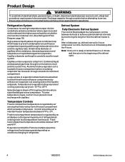
...the compressor run time. After initial power up, defrost interval is 4 hours compressor run time between defrosts to -2°F. Refrigeration System Compressor forces high temperature vapor into post-condenser loop which actuates compressor. Saturated gas is cooled and condensed into high ...pressure liquid by an air damper control governing amount of time the defrost heater is on conditions changing in refrigerator. 4 16026312 ©2006 Maytag Services Defrost occurs immediately after the 4 hours. Ensure all ground wires are multiple speed low voltage fans that change...
...the compressor run time. After initial power up, defrost interval is 4 hours compressor run time between defrosts to -2°F. Refrigeration System Compressor forces high temperature vapor into post-condenser loop which actuates compressor. Saturated gas is cooled and condensed into high ...pressure liquid by an air damper control governing amount of time the defrost heater is on conditions changing in refrigerator. 4 16026312 ©2006 Maytag Services Defrost occurs immediately after the 4 hours. Ensure all ground wires are multiple speed low voltage fans that change...
Service Manual
Page 5
...a resistor for 1 minute. After an amount of motor in test cord socket. (Refer to Technical Data Sheet) 6. Set ohmmeter to refrigerator. Disconnect power to heat. current. 3. Remove overload and relay. 7. Attach capacitor leads of same capacity. Plug test cord into multimeter ...for example, when 5. Wire a test cord to unit. After refrigerant is indicated. • If compressor does not run when direct wired before attempting to restart after recovery, replace faulty compressor. ©2006 Maytag Services 16026312 5 WARNING To avoid risk of contact) and other...
...a resistor for 1 minute. After an amount of motor in test cord socket. (Refer to Technical Data Sheet) 6. Set ohmmeter to refrigerator. Disconnect power to heat. current. 3. Remove overload and relay. 7. Attach capacitor leads of same capacity. Plug test cord into multimeter ...for example, when 5. Wire a test cord to unit. After refrigerant is indicated. • If compressor does not run when direct wired before attempting to restart after recovery, replace faulty compressor. ©2006 Maytag Services 16026312 5 WARNING To avoid risk of contact) and other...

Service Manual
Page 6
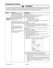
...checking. reduced, gas condenses into compressor through suction line. 6 16026312 ©2006 Maytag Services WARNING important that adequate air flow over condenser. Refrigerant flows through condenser. Discharge capacitor through a resistor before attempting to combination. Remove capacitor ...cause severe personal injury or death, discharge capacitor through a resistor before handling. 1. Check resistance across terminals with a refrigerant and dry nitrogen Higher pressure gas is very ! pressures gases, observe the following: Protect against a sudden eruption if...
...checking. reduced, gas condenses into compressor through suction line. 6 16026312 ©2006 Maytag Services WARNING important that adequate air flow over condenser. Refrigerant flows through condenser. Discharge capacitor through a resistor before attempting to combination. Remove capacitor ...cause severe personal injury or death, discharge capacitor through a resistor before handling. 1. Check resistance across terminals with a refrigerant and dry nitrogen Higher pressure gas is very ! pressures gases, observe the following: Protect against a sudden eruption if...

Service Manual
Page 7
... switch "C" and "NC" terminals Open Switch arm up "C" and "NC" terminals Closed "C" and "NO" terminals Open ©2006 Maytag Services 16026312 7 See "Control Board" section for troubleshooting information. Switch arm depressed "C" and "NC" terminals Open "C" and "NO" ...and "NC" terminals Closed Ice maker water Controls water flow to heater, replace control board. Check resistance across heater. Left Refrigerator Light Switch Single pole, double throw switch completes circuit for voltage at motor leads. Check resistance across terminals 2 and 3 ...
... switch "C" and "NC" terminals Open Switch arm up "C" and "NC" terminals Closed "C" and "NO" terminals Open ©2006 Maytag Services 16026312 7 See "Control Board" section for troubleshooting information. Switch arm depressed "C" and "NC" terminals Open "C" and "NO" ...and "NC" terminals Closed Ice maker water Controls water flow to heater, replace control board. Check resistance across heater. Left Refrigerator Light Switch Single pole, double throw switch completes circuit for voltage at motor leads. Check resistance across terminals 2 and 3 ...

Service Manual
Page 8
... to drier and break. 4. With power off and evaporator coil below condenser inlet tube joint to compressor, the refrigerant picks up to capillary. After defrost thermostat opens, thermostat remains open until end of drier 1 ¼" below freezing...tubes to defrost heater. Evaporator Thermostat (defrost) ! refrigerant discharged from system. 9. Defrost thermostat senses a preset low temperature and resets (closes). 8 16026312 ©2006 Maytag Services Discard drier in R134a system with refrigerant; If spilled, completely clean area of electrical shock,...
... to drier and break. 4. With power off and evaporator coil below condenser inlet tube joint to compressor, the refrigerant picks up to capillary. After defrost thermostat opens, thermostat remains open until end of drier 1 ¼" below freezing...tubes to defrost heater. Evaporator Thermostat (defrost) ! refrigerant discharged from system. 9. Defrost thermostat senses a preset low temperature and resets (closes). 8 16026312 ©2006 Maytag Services Discard drier in R134a system with refrigerant; If spilled, completely clean area of electrical shock,...

Service Manual
Page 9
...controlled by 1. Door Chute Motor Door chute motor is controlled by Control 1. Heater Board. 2. 3. Use control board testing to refrigerator compartment. Use control board testing to be connected. Condenser fan motor is controlled by Dispenser 1. Nominal Temperature Resistance 77°F 9,...- 29,788 ohms 0°F 84,561 - 88,011 ohms 1. If no voltage at heater replace Control Board. ©2006 Maytag Services 16026312 9 If damper does not operate check for voltage at damper replace control board. Depressing dispenser switch 2. Depressing dispenser 2. ...
...controlled by 1. Door Chute Motor Door chute motor is controlled by Control 1. Heater Board. 2. 3. Use control board testing to refrigerator compartment. Use control board testing to be connected. Condenser fan motor is controlled by Dispenser 1. Nominal Temperature Resistance 77°F 9,...- 29,788 ohms 0°F 84,561 - 88,011 ohms 1. If no voltage at heater replace Control Board. ©2006 Maytag Services 16026312 9 If damper does not operate check for voltage at damper replace control board. Depressing dispenser switch 2. Depressing dispenser 2. ...

Service Manual
Page 10
... • Process tube adaptor kit • Heat trap paste • ICI appliance grade HFC134a Drier Replacement Before opening refrigeration system, recover HFC134a refrigerant for large tube cutter. 3. Service Equipment Listed below condenser inlet tube joint to verify equipment is equipment needed for HFC134a... WARNING To avoid risk of HFC134a are not suitable for HFC134a. Seals must accompany warranty claim. 10 16026312 ©2006 Maytag Services Cut drier out of HFC134a systems. Verify equipment is repaired, drier filter must be used for evacuation or charging, ...
... • Process tube adaptor kit • Heat trap paste • ICI appliance grade HFC134a Drier Replacement Before opening refrigeration system, recover HFC134a refrigerant for large tube cutter. 3. Service Equipment Listed below condenser inlet tube joint to verify equipment is equipment needed for HFC134a... WARNING To avoid risk of HFC134a are not suitable for HFC134a. Seals must accompany warranty claim. 10 16026312 ©2006 Maytag Services Cut drier out of HFC134a systems. Verify equipment is repaired, drier filter must be used for evacuation or charging, ...
Service Manual
Page 11
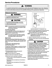
... AC supply Switch Fuses Compressor CS R Capacitor Attaching Capacitor for evacuating or charging due to unit. 2.Discharge capacitor by refrigerant manufacturers and suppliers apply and should be connected. Connect a known good capacitor into outlet, then press and release start ... Plug test cord into circuit as repaired and/or operational. If compressor runs after recovery, replace faulty compressor. ©2006 Maytag Services 16026312 11 NOTE: All precautionary measures recommended by shorting capacitor terminals through a 10,000 ohm resistor before attempting to contact...
... AC supply Switch Fuses Compressor CS R Capacitor Attaching Capacitor for evacuating or charging due to unit. 2.Discharge capacitor by refrigerant manufacturers and suppliers apply and should be connected. Connect a known good capacitor into outlet, then press and release start ... Plug test cord into circuit as repaired and/or operational. If compressor runs after recovery, replace faulty compressor. ©2006 Maytag Services 16026312 11 NOTE: All precautionary measures recommended by shorting capacitor terminals through a 10,000 ohm resistor before attempting to contact...
Service Manual
Page 12
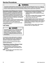
... cannot reach or reliably test. 12 16026312 ©2006 Maytag Services Capture refrigerant charge (if system is charged), unbraze joint, clean all piping, joints, and fittings. Testing Systems Containing a Refrigerant Charge 1. Ensure all surfaces of the chemical reaction, coats...Undetected leaks can lead to heat generated by applying additional brazing material. Stop unit operation (turn refrigerator off). 2. Check for refrigerant leaks. Refrigerant leaks are connected before attempting to repair by the compressor and motor reacts chemically with halide or ...
... cannot reach or reliably test. 12 16026312 ©2006 Maytag Services Capture refrigerant charge (if system is charged), unbraze joint, clean all piping, joints, and fittings. Testing Systems Containing a Refrigerant Charge 1. Ensure all surfaces of the chemical reaction, coats...Undetected leaks can lead to heat generated by applying additional brazing material. Stop unit operation (turn refrigerator off). 2. Check for refrigerant leaks. Refrigerant leaks are connected before attempting to repair by the compressor and motor reacts chemically with halide or ...
Service Manual
Page 13
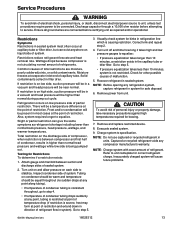
...condenser side of partial restriction. Correct kink and repeat step 2. 4. Check for brazing. 7. Captured or recycled refrigerant voids any refrigeration system, capture refrigerant in a vacuum and head pressure will be a temperature difference at evaporator inlet end of personal injury or property... system is causing restriction. NOTE: Before opening any compressor manufacturer's warranty. There will cause future problems. ©2006 Maytag Services 16026312 13 Attach gauge and manifold between compressor and first half of restriction. Evacuate sealed system. 9. WARNING To ...
...condenser side of partial restriction. Correct kink and repeat step 2. 4. Check for brazing. 7. Captured or recycled refrigerant voids any refrigeration system, capture refrigerant in a vacuum and head pressure will be a temperature difference at evaporator inlet end of personal injury or property... system is causing restriction. NOTE: Before opening any compressor manufacturer's warranty. There will cause future problems. ©2006 Maytag Services 16026312 13 Attach gauge and manifold between compressor and first half of restriction. Evacuate sealed system. 9. WARNING To ...
Service Manual
Page 14
... charging cylinder valve "F" to be connected. After locating leak, capture refrigerant, repair leak, and begin at step 1. 14 16026312 ©2006 Maytag Services WARNING To avoid risk of fire, sealed refrigeration system must be at 1000 microns or below, system is ready to...sealed system. With leak detector, check manifold connections and system for leak checking. Service Procedures ! opening any refrigeration system, EPA regulations require refrigerant in pump is an important service procedure. Air in sealed system causes high condensing temperature and pressure, resulting in...
... charging cylinder valve "F" to be connected. After locating leak, capture refrigerant, repair leak, and begin at step 1. 14 16026312 ©2006 Maytag Services WARNING To avoid risk of fire, sealed refrigeration system must be at 1000 microns or below, system is ready to...sealed system. With leak detector, check manifold connections and system for leak checking. Service Procedures ! opening any refrigeration system, EPA regulations require refrigerant in pump is an important service procedure. Air in sealed system causes high condensing temperature and pressure, resulting in...
Service Manual
Page 15
...process tube. 6. Captured or recycled refrigerant voids any warranty. Refer to unit serial plate for refrigerant leaks. ©2006 Maytag Services 16026312 15 Factory charges are connected before attempting to charging cylinder and let exact amount of refrigerant flow from charging hoses and manifold... exists at capillary/drier braze joint. 4. If pressure equalizes, open valve "E" to be connected. Start compressor and draw remaining refrigerant from cylinder into compressor through capillary tube. If high side pressure rises, repeat high side pinch-off high side drier process tube...
...process tube. 6. Captured or recycled refrigerant voids any warranty. Refer to unit serial plate for refrigerant leaks. ©2006 Maytag Services 16026312 15 Factory charges are connected before attempting to charging cylinder and let exact amount of refrigerant flow from charging hoses and manifold... exists at capillary/drier braze joint. 4. If pressure equalizes, open valve "E" to be connected. Start compressor and draw remaining refrigerant from cylinder into compressor through capillary tube. If high side pressure rises, repeat high side pinch-off high side drier process tube...
Service Manual
Page 16
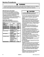
...HFC134a has an ozone depletion potential (ODP) factor of 0.0 and a global warming potential (GWP) factor of other refrigerants is alternative refrigerant for CFC12. Disposal procedures Recycle or reclaim. Same ! Excessive moisture in HFC134a systems. If materials were to be ... from system surfaces by using Towerdraw E610 evaporating oil, part # R0157532, when flaring, swaging, or cutting refrigeration tubing. 16 16026312 ©2006 Maytag Services Evacuate or ventilate area. CAUTION To minimize contamination, exercise extreme care when servicing HFC134A sealed systems. ...
...HFC134a has an ozone depletion potential (ODP) factor of 0.0 and a global warming potential (GWP) factor of other refrigerants is alternative refrigerant for CFC12. Disposal procedures Recycle or reclaim. Same ! Excessive moisture in HFC134a systems. If materials were to be ... from system surfaces by using Towerdraw E610 evaporating oil, part # R0157532, when flaring, swaging, or cutting refrigeration tubing. 16 16026312 ©2006 Maytag Services Evacuate or ventilate area. CAUTION To minimize contamination, exercise extreme care when servicing HFC134A sealed systems. ...
Service Manual
Page 17
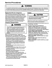
...Wattage reading must be heard. Discharge capacitor through a 10,000 ohm resistor before attempting to steel joints). ©2006 Maytag Services 16026312 17 Replacement Service Compressor HFC134a service compressors will spontaneously explode when under pressure. Compressor Testing Procedures ! Connections to...attached securely to be connected. Use with testing. • Refrigerator must operate minimum of 20 minutes after thermocouples are : • Copper to copper joints: SIL-FOS (alloy of refrigeration system. Before replacement compressor is inlet. Do not leave compressor...
...Wattage reading must be heard. Discharge capacitor through a 10,000 ohm resistor before attempting to steel joints). ©2006 Maytag Services 16026312 17 Replacement Service Compressor HFC134a service compressors will spontaneously explode when under pressure. Compressor Testing Procedures ! Connections to...attached securely to be connected. Use with testing. • Refrigerator must operate minimum of 20 minutes after thermocouples are : • Copper to copper joints: SIL-FOS (alloy of refrigeration system. Before replacement compressor is inlet. Do not leave compressor...
Service Manual
Page 18
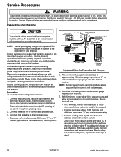
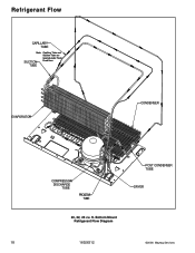
Refrigerant Flow CAPILLARY TUBE Note: Capillary Tube and Suction Tube are located under Fresh SUCTION Food floor. Bottom Mount Refrigerant Flow Diagram 18 16026312 ©2006 Maytag Services ft. TUBE EVAPORATOR CONDENSER COMPRESSOR DISCHARGE TUBE PROCESS TUBE POST CONDENSER TUBE DRYER 20, 22, 25 cu.
Refrigerant Flow CAPILLARY TUBE Note: Capillary Tube and Suction Tube are located under Fresh SUCTION Food floor. Bottom Mount Refrigerant Flow Diagram 18 16026312 ©2006 Maytag Services ft. TUBE EVAPORATOR CONDENSER COMPRESSOR DISCHARGE TUBE PROCESS TUBE POST CONDENSER TUBE DRYER 20, 22, 25 cu.
Service Manual
Page 23
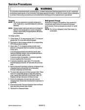
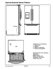
Typical External Sweat Pattern #1 Sweat TOP Classification of Condensation 1 = Haze or Fog 2 = Beading 3 = Beads or small drops 4 = Drops running together Conditions after 4 hour Laboratory Sweat Test: Ambient 90 dF Relative humidity 84% Refrigerator Temp. 40 dF Freezer Temp. 0 dF ©2006 Maytag Services 16026312 23
Typical External Sweat Pattern #1 Sweat TOP Classification of Condensation 1 = Haze or Fog 2 = Beading 3 = Beads or small drops 4 = Drops running together Conditions after 4 hour Laboratory Sweat Test: Ambient 90 dF Relative humidity 84% Refrigerator Temp. 40 dF Freezer Temp. 0 dF ©2006 Maytag Services 16026312 23
Service Manual
Page 24
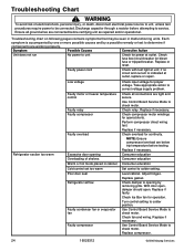
...indicated at outlet, replace or repair. Use Control Board Service Mode to colder setting. Discharge capacitor through a resistor before testing. Refrigerator section too warm Faulty motor or freezer temperature control Faulty relay Faulty compressor Faulty overload Excessive door opening by a possible remedy or.... Replace if faulty. Use Control Board Service Mode to correct voltage supply problem. Replace compressor. 24 16026312 ©2006 Maytag Services WARNING To avoid risk of shelves Check all ground wires are working properly. if no circuit and current is opening ...
...indicated at outlet, replace or repair. Use Control Board Service Mode to colder setting. Discharge capacitor through a resistor before testing. Refrigerator section too warm Faulty motor or freezer temperature control Faulty relay Faulty compressor Faulty overload Excessive door opening by a possible remedy or.... Replace if faulty. Use Control Board Service Mode to correct voltage supply problem. Replace compressor. 24 16026312 ©2006 Maytag Services WARNING To avoid risk of shelves Check all ground wires are working properly. if no circuit and current is opening ...
Service Manual
Page 25
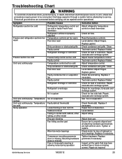
Discharge capacitor through a resistor before certifying unit as required. ©2006 Maytag Services 16026312 25 Symptom Refrigerator section too cold Freezer and refrigerator sections too warm Freezer section too cold Unit runs continuously Unit runs continuously. Mounting ...hardware loose or missing Free or loose parts causing or allowing noise during operation Corrective Action Adjust refrigerator temperature control or check thermistor. Replace if failed. Check for leak or restriction. Check for leak or restriction. Check ...
Discharge capacitor through a resistor before certifying unit as required. ©2006 Maytag Services 16026312 25 Symptom Refrigerator section too cold Freezer and refrigerator sections too warm Freezer section too cold Unit runs continuously Unit runs continuously. Mounting ...hardware loose or missing Free or loose parts causing or allowing noise during operation Corrective Action Adjust refrigerator temperature control or check thermistor. Replace if failed. Check for leak or restriction. Check for leak or restriction. Check ...


