
Service Manual
Page 3
... Pinion Gear 34 Bottom of CFC12 and HFC134a Properties ..... 16 Replacement Service Compressor 17 Compressor Testing Procedures 17 Brazing 17 Refrigerant Flow 20, 22, 25 cu. ft 19 20, 22, 25 cu. Table of Contents Important Information 2 Product Design 4 Component Testing 5 Service Procedures 10 Service Equipment 10 Drier Replacement 10 Refrigerant Precautions 11 Line Piercing... (Fully Electronic) Programming Mode 36 Defrost Operation 36 Forced Defrost Mode 36 Service Test Mode 37 Show Room Mode 40 Appendix A Owner's Manual A-1 ©2006 Maytag Services 16026312 3
... Pinion Gear 34 Bottom of CFC12 and HFC134a Properties ..... 16 Replacement Service Compressor 17 Compressor Testing Procedures 17 Brazing 17 Refrigerant Flow 20, 22, 25 cu. ft 19 20, 22, 25 cu. Table of Contents Important Information 2 Product Design 4 Component Testing 5 Service Procedures 10 Service Equipment 10 Drier Replacement 10 Refrigerant Precautions 11 Line Piercing... (Fully Electronic) Programming Mode 36 Defrost Operation 36 Forced Defrost Mode 36 Service Test Mode 37 Show Room Mode 40 Appendix A Owner's Manual A-1 ©2006 Maytag Services 16026312 3
Service Manual
Page 18
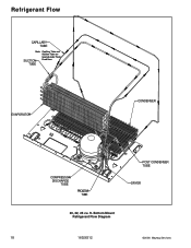
ft. Bottom Mount Refrigerant Flow Diagram 18 16026312 ©2006 Maytag Services Refrigerant Flow CAPILLARY TUBE Note: Capillary Tube and Suction Tube are located under Fresh SUCTION Food floor. TUBE EVAPORATOR CONDENSER COMPRESSOR DISCHARGE TUBE PROCESS TUBE POST CONDENSER TUBE DRYER 20, 22, 25 cu.
ft. Bottom Mount Refrigerant Flow Diagram 18 16026312 ©2006 Maytag Services Refrigerant Flow CAPILLARY TUBE Note: Capillary Tube and Suction Tube are located under Fresh SUCTION Food floor. TUBE EVAPORATOR CONDENSER COMPRESSOR DISCHARGE TUBE PROCESS TUBE POST CONDENSER TUBE DRYER 20, 22, 25 cu.
Service Manual
Page 22
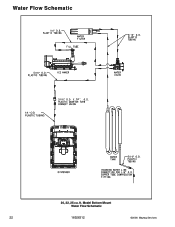
PLASTIC TUBING 1/4 " 20, 22, 25 cu. Model Bottom Mount Water Flow Schematic 22 16026312 ©2006 Maytag Services ft. Water Flow Schematic 1/4 " O.D.
PLASTIC TUBING 1/4 " 20, 22, 25 cu. Model Bottom Mount Water Flow Schematic 22 16026312 ©2006 Maytag Services ft. Water Flow Schematic 1/4 " O.D.


