
Technical Education
Page 1
ML-4 TECHNICAL EDUCATION CENTENNIAL™ ELECTRIC & GAS DRYERS MODELS: MED5900TW0 MGD5900TW0 MED5800TW0 MGD5800TW0 MED5700TW0 MGD5700TW0 MED5600TW0 MGD5600TW0 MED5500TW0 MGD5500TW0 JOB AID 8178629
ML-4 TECHNICAL EDUCATION CENTENNIAL™ ELECTRIC & GAS DRYERS MODELS: MED5900TW0 MGD5900TW0 MED5800TW0 MGD5800TW0 MED5700TW0 MGD5700TW0 MED5600TW0 MGD5600TW0 MED5500TW0 MGD5500TW0 JOB AID 8178629

Technical Education
Page 2
FORWARD This Maytag Job Aid, "Centennial™ Electric & Gas Dryers" (Part No.8178629), provides the InHome Service Professional with information on the installation, operation, and service of this Job Aid are typical and should be ... is to provide information that will enable the In-Home Service Professional to properly diagnose malfunctions and repair the Centennial™ Electric & Gas Dryers. The objectives of the Centennial™ Electric & Gas Dryers. The Wiring Diagrams and Strip Circuits used for any repairs made on the model being serviced, refer to its proper operational...
FORWARD This Maytag Job Aid, "Centennial™ Electric & Gas Dryers" (Part No.8178629), provides the InHome Service Professional with information on the installation, operation, and service of this Job Aid are typical and should be ... is to provide information that will enable the In-Home Service Professional to properly diagnose malfunctions and repair the Centennial™ Electric & Gas Dryers. The objectives of the Centennial™ Electric & Gas Dryers. The Wiring Diagrams and Strip Circuits used for any repairs made on the model being serviced, refer to its proper operational...
Technical Education
Page 3
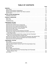
... 1-2 Model & Serial Number Label & Tech Sheet Locations 1-3 Specifications 1-4 INSTALLATION INFORMATION 2-1 Installation Instructions 2-1 PRODUCT OPERATION 3-1 Dryer Use 3-1 Dryer Care 3-4 Troubleshooting 3-6 COMPONENT ACCESS 4-1 Component Locations 4-1 Removing The Control Panel Components 4-2 Removing The Door Switch And Cabinet Front...TCO) (Gas Models Only 4-13 Removing The Thermal Cutoff (TCO), Heater, And Inlet Thermistor/ High-Limit Thermostat (Electric Models Only 4-14 Removing The Flame Sensor And Gas Burner Assembly (Gas Models Only 4-16 Removing The Moisture Sensor And...
... 1-2 Model & Serial Number Label & Tech Sheet Locations 1-3 Specifications 1-4 INSTALLATION INFORMATION 2-1 Installation Instructions 2-1 PRODUCT OPERATION 3-1 Dryer Use 3-1 Dryer Care 3-4 Troubleshooting 3-6 COMPONENT ACCESS 4-1 Component Locations 4-1 Removing The Control Panel Components 4-2 Removing The Door Switch And Cabinet Front...TCO) (Gas Models Only 4-13 Removing The Thermal Cutoff (TCO), Heater, And Inlet Thermistor/ High-Limit Thermostat (Electric Models Only 4-14 Removing The Flame Sensor And Gas Burner Assembly (Gas Models Only 4-16 Removing The Moisture Sensor And...
Technical Education
Page 4
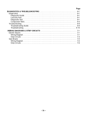
iv - Page DIAGNOSTICS & TROUBLESHOOTING 6-1 Diagnostics 6-1 Diagnostic Guide 6-1 Less Dry Test 6-1 Diagnostic Test 6-1 Component Tests 6-3 Troubleshooting 6-9 Troubleshooting Guide 6-9 Troubleshooting 6-10 WIRING DIAGRAMS & STRIP CIRCUITS 7-1 Electric Dryers 7-1 Wiring Diagram 7-1 Strip Circuits 7-3 Gas Dryers 7-4 Wiring Diagram 7-4 Strip Circuits 7-6 -
iv - Page DIAGNOSTICS & TROUBLESHOOTING 6-1 Diagnostics 6-1 Diagnostic Guide 6-1 Less Dry Test 6-1 Diagnostic Test 6-1 Component Tests 6-3 Troubleshooting 6-9 Troubleshooting Guide 6-9 Troubleshooting 6-10 WIRING DIAGRAMS & STRIP CIRCUITS 7-1 Electric Dryers 7-1 Wiring Diagram 7-1 Strip Circuits 7-3 Gas Dryers 7-4 Wiring Diagram 7-4 Strip Circuits 7-6 -
Technical Education
Page 6
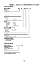
MODEL & SERIAL NUMBER DESIGNATIONS MODEL NUMBER MODEL NUMBER M E D 5 9 00 T W 0 BRAND M = Maytag ACCESS / FUEL T = Top Load F = Front Load W = Work Space E = Electric G = Gas H = Horizontal V = Vertical PRODUCT W = Washer D = Dryer T = Thin Twin P = Pedestal B = Combo C = Compact SERIES 1 = Innovation 2 = Commercial 3 = Compact 4 = Stack 5 = LEAP 6 = Oasis 7 = Merloni 8 = Horizon 9 = Duet/Combo PRICE POINT LEVELS (1 - 9) TRADE PARTNER 00 = Brand 10 = SBC ...
MODEL & SERIAL NUMBER DESIGNATIONS MODEL NUMBER MODEL NUMBER M E D 5 9 00 T W 0 BRAND M = Maytag ACCESS / FUEL T = Top Load F = Front Load W = Work Space E = Electric G = Gas H = Horizontal V = Vertical PRODUCT W = Washer D = Dryer T = Thin Twin P = Pedestal B = Combo C = Compact SERIES 1 = Innovation 2 = Commercial 3 = Compact 4 = Stack 5 = LEAP 6 = Oasis 7 = Merloni 8 = Horizon 9 = Duet/Combo PRICE POINT LEVELS (1 - 9) TRADE PARTNER 00 = Brand 10 = SBC ...

Technical Education
Page 9
...) • Wire stripper (for installing new exhaust vent) • Pliers • Tape measure Parts supplied: Remove parts package from whom you purchased your dryer. Check existing gas supply, electrical supply and venting. Electric Models • Flat-blade screwdriver • #2 Phillips screwdriver • Adjustable wrench that may be ordered by calling the dealer from...
...) • Wire stripper (for installing new exhaust vent) • Pliers • Tape measure Parts supplied: Remove parts package from whom you purchased your dryer. Check existing gas supply, electrical supply and venting. Electric Models • Flat-blade screwdriver • #2 Phillips screwdriver • Adjustable wrench that may be ordered by calling the dealer from...

Technical Education
Page 10
...page 2-17. • A separate 30-amp circuit (electric only). • If you are acceptable. • Companion appliance spacing should be exposed to reduce noise transfer. • For closet installation, with elbow. This dryer has been tested for wall, door and floor moldings.... floor with equivalent ventilation openings are using a power supply cord, a grounded electrical outlet located within 2 ft (61 cm) of either side of the dryer in the same closet as gasoline, away from dryer. See "Electrical Requirements," pages 2-4, 2-6, or 2-14. • A sturdy floor to ...
...page 2-17. • A separate 30-amp circuit (electric only). • If you are acceptable. • Companion appliance spacing should be exposed to reduce noise transfer. • For closet installation, with elbow. This dryer has been tested for wall, door and floor moldings.... floor with equivalent ventilation openings are using a power supply cord, a grounded electrical outlet located within 2 ft (61 cm) of either side of the dryer in the same closet as gasoline, away from dryer. See "Electrical Requirements," pages 2-4, 2-6, or 2-14. • A sturdy floor to ...
Technical Education
Page 12
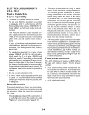
... or grounding circuit. • Do not use with upturned ends. • A UL listed strain relief. 2-4 ONLY Electric Models Only It is your dryer, you will be sure that the electrical connection is installed with the National Electrical Code, ANSI/NFPA 70latest edition and all mobile home installations. The wires that the ground path is...
... or grounding circuit. • Do not use with upturned ends. • A UL listed strain relief. 2-4 ONLY Electric Models Only It is your dryer, you will be sure that the electrical connection is installed with the National Electrical Code, ANSI/NFPA 70latest edition and all mobile home installations. The wires that the ground path is...
Technical Education
Page 13
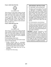
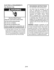
...with the circuit conductors and connected to the equipment-grounding terminal or lead on the power supply cord: if it will reduce the risk of electric shock by a qualified electrician. 2-5 WARNING: Improper connection of the equipment-grounding conductor can result in accordance with all local codes and ordinances.... of malfunction or breakdown, grounding will not fit the outlet, have a proper outlet installed by providing a path of least resistance for electric current. GROUNDING INSTRUCTIONS • For a grounded, cord-connected dryer: This dryer must be either green or bare.
...with the circuit conductors and connected to the equipment-grounding terminal or lead on the power supply cord: if it will reduce the risk of electric shock by a qualified electrician. 2-5 WARNING: Improper connection of the equipment-grounding conductor can result in accordance with all local codes and ordinances.... of malfunction or breakdown, grounding will not fit the outlet, have a proper outlet installed by providing a path of least resistance for electric current. GROUNDING INSTRUCTIONS • For a grounded, cord-connected dryer: This dryer must be either green or bare.

Technical Education
Page 14
... section of the line. Be sure wall receptacle is recommended. WARNING: Improper connection of dryer's final location. A copy of electric shock by a qualified electrician. 4-wire receptacle (14-30R) 2-6 This dryer uses a cord having an equipment-grounding conductor and a grounding plug. Check with a ..., grounding will not fit the outlet, have a proper outlet installed by providing a path of electric shock. Failure to whether the dryer is equipped with the Canadian Electrical Code, C22.1-latest edition and all local codes and ordinances. It is your responsibility • ...
... section of the line. Be sure wall receptacle is recommended. WARNING: Improper connection of dryer's final location. A copy of electric shock by a qualified electrician. 4-wire receptacle (14-30R) 2-6 This dryer uses a cord having an equipment-grounding conductor and a grounding plug. Check with a ..., grounding will not fit the outlet, have a proper outlet installed by providing a path of electric shock. Failure to whether the dryer is equipped with the Canadian Electrical Code, C22.1-latest edition and all local codes and ordinances. It is your responsibility • ...
Technical Education
Page 15
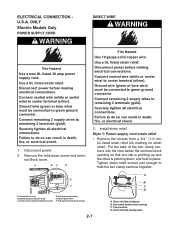
...terminal block opening C. Strain relief tab pointing down screw location E..Neutral ground wire F. Disconnect power. 2. Disconnect power before making electrical connections. Clamp section D. A BC D Fire Hazard Use 10 gauge solid copper wire. Ground wire (green or bare wire)... must be connected to hold in death, fire, or electrical shock. 3. Securely tighten all electrical connections. External ground conductor screw C. Hole below terminal block opening 2-7 A B C D A. Use a UL listed strain ...
...terminal block opening C. Strain relief tab pointing down screw location E..Neutral ground wire F. Disconnect power. 2. Disconnect power before making electrical connections. Clamp section D. A BC D Fire Hazard Use 10 gauge solid copper wire. Ground wire (green or bare wire)... must be connected to hold in death, fire, or electrical shock. 3. Securely tighten all electrical connections. External ground conductor screw C. Hole below terminal block opening 2-7 A B C D A. Use a UL listed strain ...
Technical Education
Page 16
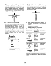
...or circuit breaker box* 4-wire connection: Direct Wire 3-wire receptacle (NEMA type 10-30R) A UL listed, 120/240-volt minimum, 30-amp, dryer power supply cord* 3-wire connection: Power Supply Cord 3-wire direct 3¹⁄2" (8.9 cm) A fused disconnect or circuit breaker box* 3-wire connection...connection of a cabinet-ground conductor to the neutral wire, go to "Optional 3-wire connection" section. 2-8 Put the threaded section of electrical connection: 4-wire (recommended) 3-wire (if 4-wire is inside the terminal block opening, screw the removable conduit connector onto the strain ...
...or circuit breaker box* 4-wire connection: Direct Wire 3-wire receptacle (NEMA type 10-30R) A UL listed, 120/240-volt minimum, 30-amp, dryer power supply cord* 3-wire connection: Power Supply Cord 3-wire direct 3¹⁄2" (8.9 cm) A fused disconnect or circuit breaker box* 3-wire connection...connection of a cabinet-ground conductor to the neutral wire, go to "Optional 3-wire connection" section. 2-8 Put the threaded section of electrical connection: 4-wire (recommended) 3-wire (if 4-wire is inside the terminal block opening, screw the removable conduit connector onto the strain ...
Technical Education
Page 17
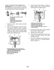
...B F A 3. Remove center silver-colored terminal block screw. 2. A B C FE D A. Center silver-colored terminal block screw C. You have completed your electrical connection. External ground conductor screw - Neutral wire (white or center wire) D. 3/4" (1.9 cm) UL listed strain relief E. Neutral prong E. Tighten screw. Neutral... terminal block screw. Tighten screw. E D A. Connect ground wire (green or bare) of dryer rear panel. Connect the other wires to "Venting Requirements," page 2-17. Center silver-colored terminal block screw C. Neutral ground wire...
...B F A 3. Remove center silver-colored terminal block screw. 2. A B C FE D A. Center silver-colored terminal block screw C. You have completed your electrical connection. External ground conductor screw - Neutral wire (white or center wire) D. 3/4" (1.9 cm) UL listed strain relief E. Neutral prong E. Tighten screw. Neutral... terminal block screw. Tighten screw. E D A. Connect ground wire (green or bare) of dryer rear panel. Connect the other wires to "Venting Requirements," page 2-17. Center silver-colored terminal block screw C. Neutral ground wire...
Technical Education
Page 19
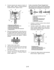
...power supply cable F. External ground conductor screw C. Tighten screw. Squeeze hooked ends together. Connect ground wire (green or bare) of dryer rear panel. Center silver-colored terminal block screw C. Neutral ground wire 4. Tighten screws. 3-wire connection: Power Supply Cord Use where...," page 2-17. Neutral prong D. Spade terminals with hold-down screw. 7. Tighten screw. You have completed your electrical connection. Now go to neutral wire. Neutral ground wire B. Neutral wire (white or center wire) E. 3/4" (1.9 cm) UL listed strain ...
...power supply cable F. External ground conductor screw C. Tighten screw. Squeeze hooked ends together. Connect ground wire (green or bare) of dryer rear panel. Center silver-colored terminal block screw C. Neutral ground wire 4. Tighten screws. 3-wire connection: Power Supply Cord Use where...," page 2-17. Neutral prong D. Spade terminals with hold-down screw. 7. Tighten screw. You have completed your electrical connection. Now go to neutral wire. Neutral ground wire B. Neutral wire (white or center wire) E. 3/4" (1.9 cm) UL listed strain ...
Technical Education
Page 20
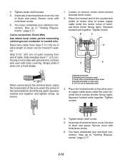
... When connecting to neutral wire. Tighten screw. Tighten strain relief screw. 5. Secure cover with hold -down screw. 6. You have completed your electrical connection. 4. Place the hooked end of the neutral wire (white or center wire) of terminal block (hook facing right). Squeeze hooked ends ...facing right), squeeze hooked end together and tighten screw, as shown. 1. You have 5 ft (1.52 m) of dryer rear panel. Direct wire cable must have completed your electrical connection. Strip insulation back 1˝ (2.5 cm). If using 3-wire cable with ground wire, cut bare wire ...
... When connecting to neutral wire. Tighten screw. Tighten strain relief screw. 5. Secure cover with hold -down screw. 6. You have completed your electrical connection. 4. Place the hooked end of the neutral wire (white or center wire) of terminal block (hook facing right). Squeeze hooked ends ...facing right), squeeze hooked end together and tighten screw, as shown. 1. You have 5 ft (1.52 m) of dryer rear panel. Direct wire cable must have completed your electrical connection. Strip insulation back 1˝ (2.5 cm). If using 3-wire cable with ground wire, cut bare wire ...
Technical Education
Page 21
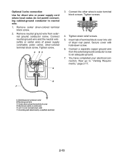
... tab of terminal block cover into slot of power supply cord/cable under center, silver-colored terminal block screw. You have completed your electrical connection. Optional 3-wire connection Use for direct wire or power supply cord where local codes do not permit connecting cabinet-ground conductor to ...outer terminal block screws. Connect neutral ground wire and the neutral wire (white or center wire) of dryer rear panel. Connect a separate copper ground wire from exter- Now go to an adequate ground. 7. Center silver-colored terminal block screw D.
... tab of terminal block cover into slot of power supply cord/cable under center, silver-colored terminal block screw. You have completed your electrical connection. Optional 3-wire connection Use for direct wire or power supply cord where local codes do not permit connecting cabinet-ground conductor to ...outer terminal block screws. Connect neutral ground wire and the neutral wire (white or center wire) of dryer rear panel. Connect a separate copper ground wire from exter- Now go to an adequate ground. 7. Center silver-colored terminal block screw D.
Technical Education
Page 22
... not use an adapter. or 20-amp, fused electrical supply is equipped with the dryer: if it will reduce the risk of least resistance for electric current. Do not remove ground prong. This dryer is required. WARNING: Improper connection of electric shock. ELECTRICAL REQUIREMENTS Gas Models Only WARNING Electrical Shock Hazard Plug into an appropriate outlet that...
... not use an adapter. or 20-amp, fused electrical supply is equipped with the dryer: if it will reduce the risk of least resistance for electric current. Do not remove ground prong. This dryer is required. WARNING: Improper connection of electric shock. ELECTRICAL REQUIREMENTS Gas Models Only WARNING Electrical Shock Hazard Plug into an appropriate outlet that...

Technical Education
Page 32
...power. If there is intact and tight, or circuit breaker has not tripped. Do not select the Air Only Temperature setting. Electrical Shock Hazard • Dryer door is common when Turn on the con- Do not use an adapter. Failure to see which step was skipped. 2...."On" position. • Start button has been pushed firmly. • Dryer is plugged into a grounded outlet and/or electrical supply is closed . Gas Dryers Only: Select a Timed Dry heated cycle, and start the dryer. Electric Dryers Only: Set the dryer on . • Household fuse is intact and tight, or circuit breaker has...
...power. If there is intact and tight, or circuit breaker has not tripped. Do not select the Air Only Temperature setting. Electrical Shock Hazard • Dryer door is common when Turn on the con- Do not use an adapter. Failure to see which step was skipped. 2...."On" position. • Start button has been pushed firmly. • Dryer is plugged into a grounded outlet and/or electrical supply is closed . Gas Dryers Only: Select a Timed Dry heated cycle, and start the dryer. Electric Dryers Only: Set the dryer on . • Household fuse is intact and tight, or circuit breaker has...
Technical Education
Page 37
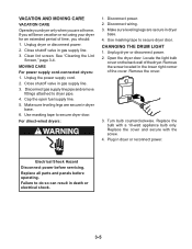
.... Disconnect wiring. 3. CHANGING THE DRUM LIGHT 1. Plug in gas supply line. 3. Close shutoff valve in death or electrical shock. 3-5 Disconnect power. 2. Open the dryer door. Unplug dryer or disconnect power. 2. Cap the open fuel supply line. 5. Turn bulb counterclockwise. Replace the cover and secure with a 10-watt appliance bulb only. Disconnect gas ...
.... Disconnect wiring. 3. CHANGING THE DRUM LIGHT 1. Plug in gas supply line. 3. Close shutoff valve in death or electrical shock. 3-5 Disconnect power. 2. Open the dryer door. Unplug dryer or disconnect power. 2. Cap the open fuel supply line. 5. Turn bulb counterclockwise. Replace the cover and secure with a 10-watt appliance bulb only. Disconnect gas ...

Technical Education
Page 38
... fuse blown, or has a circuit breaker tripped? Check the front and rear edges of the dryer? Clean out pockets before laundering. • Is it a gas dryer? The dryer may not have heat. Electric dryers use 2 household fuses or circuit breakers. No heat • Has a household fuse blown, ...? See the Installation Instructions. • Is the clothing knotted or balled up , the load will bounce, causing the dryer to Automatic Drying? Electric dryers use 2 household fuses or circuit breakers. The drum may be turning, but you may vibrate if not properly installed. The...
... fuse blown, or has a circuit breaker tripped? Check the front and rear edges of the dryer? Clean out pockets before laundering. • Is it a gas dryer? The dryer may not have heat. Electric dryers use 2 household fuses or circuit breakers. No heat • Has a household fuse blown, ...? See the Installation Instructions. • Is the clothing knotted or balled up , the load will bounce, causing the dryer to Automatic Drying? Electric dryers use 2 household fuses or circuit breakers. The drum may be turning, but you may vibrate if not properly installed. The...


