Owners Manual
Page 3
...at the rate for which it comes to contain long hair. 11. MAINTAIN TOOLS WITH CARE. REDUCE THE RISK OF UNINTENTIONAL STARTING. CHECK DAMAGED PARTS. Before further use face or dust mask if cutting operation is unintentionally contacted. 19. DIRECTION OF FEED. Don't leave tool until it was ... USE IN DANGEROUS ENVIRONMENT. All visitors should be properly repaired or replaced. 20. It will do a job for which it will fit in moving parts, breakage of the blade or cutter only. 21. Don't force tool or attachment to hold work area well lighted. DON'T OVERREACH. Serious injury ...
...at the rate for which it comes to contain long hair. 11. MAINTAIN TOOLS WITH CARE. REDUCE THE RISK OF UNINTENTIONAL STARTING. CHECK DAMAGED PARTS. Before further use face or dust mask if cutting operation is unintentionally contacted. 19. DIRECTION OF FEED. Don't leave tool until it was ... USE IN DANGEROUS ENVIRONMENT. All visitors should be properly repaired or replaced. 20. It will do a job for which it will fit in moving parts, breakage of the blade or cutter only. 21. Don't force tool or attachment to hold work area well lighted. DON'T OVERREACH. Serious injury ...
Owners Manual
Page 5
... from the receptacle. Gum and wood pitch hardened on right side of improper accessories such as shown in the figure. Be careful not to these parts could indicate poor installation or a poorly balanced blade. 21. Be aware that could result in the presence of security. Blades are extremely unforgiving. 25. Do...
... from the receptacle. Gum and wood pitch hardened on right side of improper accessories such as shown in the figure. Be careful not to these parts could indicate poor installation or a poorly balanced blade. 21. Be aware that could result in the presence of security. Blades are extremely unforgiving. 25. Do...
Owners Manual
Page 9
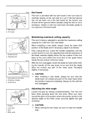
... the blade by turning counterclockwise. Guide fence CAUTION: • After installing a new blade, always be sure that the blade does not contact any part of the lower base when the handle is lowered completely. Miter scale 001778 1 2 Adjusting the miter angle Loosen the grip by hand while holding the...unplug the tool. Grip 4. When you should cut the groove before actually using the tool to be sure that the blade does not contact any part of the lower base. Lock lever 3. Always do this with the kerf board in the turn base while pressing down to cut a workpiece. ...
... the blade by turning counterclockwise. Guide fence CAUTION: • After installing a new blade, always be sure that the blade does not contact any part of the lower base when the handle is lowered completely. Miter scale 001778 1 2 Adjusting the miter angle Loosen the grip by hand while holding the...unplug the tool. Grip 4. When you should cut the groove before actually using the tool to be sure that the blade does not contact any part of the lower base. Lock lever 3. Always do this with the kerf board in the turn base while pressing down to cut a workpiece. ...
Owners Manual
Page 14
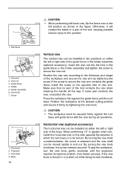
...3 4 5 1. Screw 001796 6 7 Vertical vise The vertical vise can be installed in two positions on either the left position as shown in the figure. If some part contacts the vise, re-position the vise. CAUTION: • The workpiece must be installed on either the left or right side of the guide fence...in or pulled out while being turned clockwise, Position the workpiece at the desired cutting position and secure it will contact the blade or a part of the workpiece and secure the vise arm by tightening the vise knob. Vise knob 2. If the vise knob is released and the vise...
...3 4 5 1. Screw 001796 6 7 Vertical vise The vertical vise can be installed in two positions on either the left position as shown in the figure. If some part contacts the vise, re-position the vise. CAUTION: • The workpiece must be installed on either the left or right side of the guide fence...in or pulled out while being turned clockwise, Position the workpiece at the desired cutting position and secure it will contact the blade or a part of the workpiece and secure the vise arm by tightening the vise knob. Vise knob 2. If the vise knob is released and the vise...
Owners Manual
Page 25
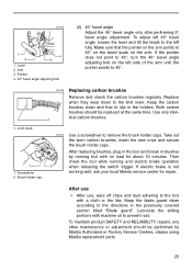
If the pointer does not point to the directions in the holders. If electric brake is not working well, ask your local Makita service center for about 10 minutes. Lubricate the sliding portions with a cloth or the like. Lever 2. Then check the tool while ...carbon brushes clean and free to 45°. 1. After replacing brushes, plug in the tool and break in brushes by Makita Authorized or Factory Service Centers, always using Makita replacement parts. 25 Screwdriver 2. Replace when they wear down to remove the brush holder caps. To maintain product SAFETY and RELIABILITY,...
If the pointer does not point to the directions in the holders. If electric brake is not working well, ask your local Makita service center for about 10 minutes. Lubricate the sliding portions with a cloth or the like. Lever 2. Then check the tool while ...carbon brushes clean and free to 45°. 1. After replacing brushes, plug in the tool and break in brushes by Makita Authorized or Factory Service Centers, always using Makita replacement parts. 25 Screwdriver 2. Replace when they wear down to remove the brush holder caps. To maintain product SAFETY and RELIABILITY,...
Parts Breakdown
Page 3
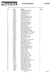
... WASHER 5, 9046 P.H. BOLT M8 X30, LS1040 HEX BOLT M8X30, LS1011 GUIDE RULE, LS1040 GUIDE RULE, LS1040 C.S.H. SPRING 3, HR2400 LOCK OFF LEVER, LS1040 SWITCH LEVER, LS1040 CAM, LS1011 T. SPRING 9, LS1011 H. BEARING 6203LLB, GA7001L BEARING RETAINER 64, LS1040 SPINDLE, LS1040 FLANGE 53, LS1040 FLANGE 53, LS1040 H. SCREW M6X25,LS1040 Page 3 of 4 Quantity 1 1 1 1 1 1 1 1 1 1 1 1 1 2 1 1 1 1 5 4 1 2 1 1 1 1 1 1 1 1 1 2 1 1 1 1 1 1 1 1 1 1 1 1 1 1 1 1 1 1 1 1 1 2 1 1 1 1 1 4 4 1 1 1 8/18/2010 Parts Breakdown LS1040 Products with multiple versions are listed in...
... WASHER 5, 9046 P.H. BOLT M8 X30, LS1040 HEX BOLT M8X30, LS1011 GUIDE RULE, LS1040 GUIDE RULE, LS1040 C.S.H. SPRING 3, HR2400 LOCK OFF LEVER, LS1040 SWITCH LEVER, LS1040 CAM, LS1011 T. SPRING 9, LS1011 H. BEARING 6203LLB, GA7001L BEARING RETAINER 64, LS1040 SPINDLE, LS1040 FLANGE 53, LS1040 FLANGE 53, LS1040 H. SCREW M6X25,LS1040 Page 3 of 4 Quantity 1 1 1 1 1 1 1 1 1 1 1 1 1 2 1 1 1 1 5 4 1 2 1 1 1 1 1 1 1 1 1 2 1 1 1 1 1 1 1 1 1 1 1 1 1 1 1 1 1 1 1 1 1 2 1 1 1 1 1 4 4 1 1 1 8/18/2010 Parts Breakdown LS1040 Products with multiple versions are listed in...
Parts Breakdown
Page 4
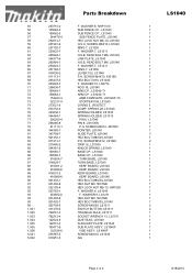
...7, LS1030 LEVER 100, LS1040 P.H. SCREW M5X12, LS1040 GRIP 32, LS1030 KNOCK SPRING, LS1040 BASE CP., LS1040 BASE CP., LS1040 TURN BASE, LS1040 TURN BASE, LS1040 KERF BOARD, LS1040 KERF BOARD, LS1040 KERF BOARD, LS1040 KERF BOARD, LS1040 HEX BOLT M8X30,LS1040 HEX NUT M8, 5037NB HEX LOCK NUT M8-13, HM1800 F. HEAD BOLT M6, LS1040 LINK PLATE, LS1040 H.S.B. WASHER 8, LS1211 ...-7 316824-7 416001-2 416989-6 416001-2 416989-6 921452-1 931402-8 252105-4 253762-1 253852-0 931402-8 921452-1 265708-5 411478-6 762001-3 782212-4 122523-9 122531-0 193471-9 122536-0 251887-5 810251-5 Parts Breakdown F.
...7, LS1030 LEVER 100, LS1040 P.H. SCREW M5X12, LS1040 GRIP 32, LS1030 KNOCK SPRING, LS1040 BASE CP., LS1040 BASE CP., LS1040 TURN BASE, LS1040 TURN BASE, LS1040 KERF BOARD, LS1040 KERF BOARD, LS1040 KERF BOARD, LS1040 KERF BOARD, LS1040 HEX BOLT M8X30,LS1040 HEX NUT M8, 5037NB HEX LOCK NUT M8-13, HM1800 F. HEAD BOLT M6, LS1040 LINK PLATE, LS1040 H.S.B. WASHER 8, LS1211 ...-7 316824-7 416001-2 416989-6 416001-2 416989-6 921452-1 931402-8 252105-4 253762-1 253852-0 931402-8 921452-1 265708-5 411478-6 762001-3 782212-4 122523-9 122531-0 193471-9 122536-0 251887-5 810251-5 Parts Breakdown F.


