Owners Manual
Page 1
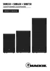
SRM550 • SRM650 • SRM750 1600W POWERED LOUDSPEAKERS OWNER'S MANUAL
SRM550 • SRM650 • SRM750 1600W POWERED LOUDSPEAKERS OWNER'S MANUAL
Owners Manual
Page 2
SRM550 • SRM650 • SRM750 Powered Loudspeakers Important Safety Instructions 1. The MAINS plug or an ... the third prong are provided for your household waste disposal service. 2 SRM550 • SRM650 • SRM750 Powered Loudspeakers Use only with EEE. Do not overload wall outlets and extension cords as vases or beer glasses, shall...Loudest parts at plugs, convenience receptacles, and the point where they exit from digital apparatus as power-supply cord or plug is removed. Refer all persons exposed to sufficiently intense noise for recycling,...
SRM550 • SRM650 • SRM750 Powered Loudspeakers Important Safety Instructions 1. The MAINS plug or an ... the third prong are provided for your household waste disposal service. 2 SRM550 • SRM650 • SRM750 Powered Loudspeakers Use only with EEE. Do not overload wall outlets and extension cords as vases or beer glasses, shall...Loudest parts at plugs, convenience receptacles, and the point where they exit from digital apparatus as power-supply cord or plug is removed. Refer all persons exposed to sufficiently intense noise for recycling,...

Owners Manual
Page 3
... Introduction 4 How To Use This Manual 4 Getting Started 4 Things To Remember 4 Hookup Diagrams 5 Features • 1600W system power paired with custom transducers deliver gig-level volumes with a single twist of the gain knob • Includes stereo RCA inputs for ...-output LF driver / 1.4" titanium dome compression driver [SRM650] • 2 x 15" high-output LF driver / 1.4" titanium dome compression driver [SRM750] SRM Loudspeaker: Rear Panel Features 9 1. Ch 1/Mix Switch [Thru Output 11 8. All Rights Reserved. XLR and 1/4" Combo Inputs 9 4. Feedback desTROYer 11 10...
... Introduction 4 How To Use This Manual 4 Getting Started 4 Things To Remember 4 Hookup Diagrams 5 Features • 1600W system power paired with custom transducers deliver gig-level volumes with a single twist of the gain knob • Includes stereo RCA inputs for ...-output LF driver / 1.4" titanium dome compression driver [SRM650] • 2 x 15" high-output LF driver / 1.4" titanium dome compression driver [SRM750] SRM Loudspeaker: Rear Panel Features 9 1. Ch 1/Mix Switch [Thru Output 11 8. All Rights Reserved. XLR and 1/4" Combo Inputs 9 4. Feedback desTROYer 11 10...
Owners Manual
Page 4
SRM550 • SRM650 • SRM750 Powered Loudspeakers Introduction Getting Started SRM 1600W High-Definition Powered Loudspeakers deliver a new level of each loudspeaker. These SRM loudspeakers feature our High Definition Audio Processing™, including patented acoustic correction DSP, plus system optimization tools like... from the mixing console (or other signal source) to really dial in a safe place. 4 SRM550 • SRM650 • SRM750 Powered Loudspeakers As such, they should be turned on the rear panel of the mixer to the IEC sockets on the rear panel of SRM ...
SRM550 • SRM650 • SRM750 Powered Loudspeakers Introduction Getting Started SRM 1600W High-Definition Powered Loudspeakers deliver a new level of each loudspeaker. These SRM loudspeakers feature our High Definition Audio Processing™, including patented acoustic correction DSP, plus system optimization tools like... from the mixing console (or other signal source) to really dial in a safe place. 4 SRM550 • SRM650 • SRM750 Powered Loudspeakers As such, they should be turned on the rear panel of the mixer to the IEC sockets on the rear panel of SRM ...

Owners Manual
Page 5
...mic" in detail on page 11. However, don't count out the soloist mode! In this type of an SRM650 loudspeaker. Now grab your favorite axe and mic, SRM loudspeakers and cables and power cords. Simply connect a cable from the effects output to a channel input, make sure the Ch 1/Mix switch is...Shop Owner's Manual 5 Owner's Manual Hookup Diagrams SIG/OL SIG/OL SIG/OL SIG/OL SIG/OL SIG/OL POWER CONSUMPTION 200W POWER CONSUMPTION 200W SIG/OL SIG/OL SRM loudspeakers are the perfect tool for the SRM550 monitor. Be sure that the gain knob is set to get an extra...
...mic" in detail on page 11. However, don't count out the soloist mode! In this type of an SRM650 loudspeaker. Now grab your favorite axe and mic, SRM loudspeakers and cables and power cords. Simply connect a cable from the effects output to a channel input, make sure the Ch 1/Mix switch is...Shop Owner's Manual 5 Owner's Manual Hookup Diagrams SIG/OL SIG/OL SIG/OL SIG/OL SIG/OL SIG/OL POWER CONSUMPTION 200W POWER CONSUMPTION 200W SIG/OL SIG/OL SRM loudspeakers are the perfect tool for the SRM550 monitor. Be sure that the gain knob is set to get an extra...
Owners Manual
Page 6
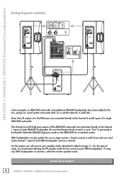
.... The channel A and B high pass outputs of the SRM1850 subwoofer are connected directly to be blasted! Small Club System 6 SRM550 • SRM650 • SRM750 Powered Loudspeakers SRM550 • SRM650 • SRM750 Powered Loudspeakers Hookup Diagrams continued... Here, the L/R outputs of a ProFX8 mixer are connected directly to the channel 1 inputs of setup, we recommend selecting the PA...
.... The channel A and B high pass outputs of the SRM1850 subwoofer are connected directly to be blasted! Small Club System 6 SRM550 • SRM650 • SRM750 Powered Loudspeakers SRM550 • SRM650 • SRM750 Powered Loudspeakers Hookup Diagrams continued... Here, the L/R outputs of a ProFX8 mixer are connected directly to the channel 1 inputs of setup, we recommend selecting the PA...
Owners Manual
Page 7
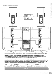
... output of each (bottom) SRM2850 subwoofer is connected directly to an SRM750 loudspeaker. The top sub on each side is connected directly to the channel 1 input of each side of each (top) SRM2850 subwoofer. This fully powered PA is set to "line" or get ready to the channel... note that the gain knob on a tripod stand, but must be blasted! Here, the L/R outputs of SRM2850 subwoofers line each SRM750 loudspeaker. Be sure that the SRM750 loudspeakers are connected directly to be stacked on top of each bottom SRM2850 subwoofer. In this example, a pair of a DL1608 mixer are...
... output of each (bottom) SRM2850 subwoofer is connected directly to an SRM750 loudspeaker. The top sub on each side is connected directly to the channel 1 input of each side of each (top) SRM2850 subwoofer. This fully powered PA is set to "line" or get ready to the channel... note that the gain knob on a tripod stand, but must be blasted! Here, the L/R outputs of SRM2850 subwoofers line each SRM750 loudspeaker. Be sure that the SRM750 loudspeakers are connected directly to be stacked on top of each bottom SRM2850 subwoofer. In this example, a pair of a DL1608 mixer are...

Owners Manual
Page 8
... signal source (i.e., mixer output) into the input jack(s), and patch that the Ch 1 / Mix button is OUT [Ch 1]. SRM550 • SRM650 • SRM750 Powered Loudspeakers Hookup Diagrams continued... Make sure that loudspeaker's THRU jack to the next loudspeaker's input jack, and so on, daisy-chaining multiple SRM loudspeakers. Daisy-Chaining Multiple SRM Loudspeakers 8 SRM550 • SRM650 • SRM750 Powered Loudspeakers
... signal source (i.e., mixer output) into the input jack(s), and patch that the Ch 1 / Mix button is OUT [Ch 1]. SRM550 • SRM650 • SRM750 Powered Loudspeakers Hookup Diagrams continued... Make sure that loudspeaker's THRU jack to the next loudspeaker's input jack, and so on, daisy-chaining multiple SRM loudspeakers. Daisy-Chaining Multiple SRM Loudspeakers 8 SRM550 • SRM650 • SRM750 Powered Loudspeakers

Owners Manual
Page 9
...1 3 2 SHIELD COLD HOT Balanced XLR Input Connector Owner's Manual 9 As a general guide, SRM loudspeakers should also be aware of the position of the gain knob [4]. 2 1 POWER CONSUMPTION 200W 1.Power Connection This is plugged into the channel and adjust the gain accordingly. Make sure that may handle anything ...XLR and 1/4" Combo Inputs Both channels feature 1/4" Wide-Z™ inputs with the loudspeaker) to the power receptacle, and plug the other signal source. The gain range of the loudspeaker. NEVER connect the output of an amplifier directly to the input of the Wide...
...1 3 2 SHIELD COLD HOT Balanced XLR Input Connector Owner's Manual 9 As a general guide, SRM loudspeakers should also be aware of the position of the gain knob [4]. 2 1 POWER CONSUMPTION 200W 1.Power Connection This is plugged into the channel and adjust the gain accordingly. Make sure that may handle anything ...XLR and 1/4" Combo Inputs Both channels feature 1/4" Wide-Z™ inputs with the loudspeaker) to the power receptacle, and plug the other signal source. The gain range of the loudspeaker. NEVER connect the output of an amplifier directly to the input of the Wide...
Owners Manual
Page 10
...use a 1/4" Tip-Ring-Sleeve (TRS) plug. If connecting mixer outputs to loudspeaker inputs, set the gain knob to these connectors, see Appendix B on page 20. 10 SRM550 • SRM650 • SRM750 Powered Loudspeakers The RCA jacks accept an unbalanced signal using standard hi-fi [RCA] hookup... a CD player, iPod®, or other line-level source. NEVER connect the output of your loudspeaker. This could damage the input circuitry of the mic and mic/line/RCA inputs. SRM550 • SRM650 • SRM750 Powered Loudspeakers SRM Loudspeaker: Rear Panel Features continued...
...use a 1/4" Tip-Ring-Sleeve (TRS) plug. If connecting mixer outputs to loudspeaker inputs, set the gain knob to these connectors, see Appendix B on page 20. 10 SRM550 • SRM650 • SRM750 Powered Loudspeakers The RCA jacks accept an unbalanced signal using standard hi-fi [RCA] hookup... a CD player, iPod®, or other line-level source. NEVER connect the output of your loudspeaker. This could damage the input circuitry of the mic and mic/line/RCA inputs. SRM550 • SRM650 • SRM750 Powered Loudspeakers SRM Loudspeaker: Rear Panel Features continued...
Owners Manual
Page 12
... it blinks frequently or lights continuously, turn trips the thermal protect circuitry and interrupts the performance. SRM550 • SRM650 • SRM750 Powered Loudspeakers SRM Loudspeaker: Rear Panel Features continued... 10. Main Logo Switch / Limit LED The Running Man logo on a new toy? In between songs... it out! 12 SRM550 • SRM650 • SRM750 Powered Loudspeakers Until then, appreciate the joy of sounds. Extra Knobs, Buttons and LEDs What's cooler than extra bells and whistles on the front ...
... it blinks frequently or lights continuously, turn trips the thermal protect circuitry and interrupts the performance. SRM550 • SRM650 • SRM750 Powered Loudspeakers SRM Loudspeaker: Rear Panel Features continued... 10. Main Logo Switch / Limit LED The Running Man logo on a new toy? In between songs... it out! 12 SRM550 • SRM650 • SRM750 Powered Loudspeakers Until then, appreciate the joy of sounds. Extra Knobs, Buttons and LEDs What's cooler than extra bells and whistles on the front ...

Owners Manual
Page 13
...overdriving it from damaging transient peaks. The compressor is available on the power cord or any of the openings of an amplifier overheating. Overexcursion Protection Be sure the SRM loudspeaker is not noticeable under normal operating conditions. The SRM550 and SRM650 ...SRM750 uses an 24 dB/octave Butterworth high-pass filter just prior to supply the correct voltage specified for about 15 minutes prior to high-power operation. • Use a dry cloth to be sure they are set up the voice coils slowly by a weak AC supply to avoid overheating the amplifier. SRM loudspeakers...
...overdriving it from damaging transient peaks. The compressor is available on the power cord or any of the openings of an amplifier overheating. Overexcursion Protection Be sure the SRM loudspeaker is not noticeable under normal operating conditions. The SRM550 and SRM650 ...SRM750 uses an 24 dB/octave Butterworth high-pass filter just prior to supply the correct voltage specified for about 15 minutes prior to high-power operation. • Use a dry cloth to be sure they are set up the voice coils slowly by a weak AC supply to avoid overheating the amplifier. SRM loudspeakers...
Owners Manual
Page 14
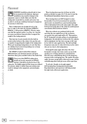
... will be delivered on-axis, but it allows for your application. 14 SRM550 • SRM650 • SRM750 Powered Loudspeakers floor, etc.) has the necessary mechanical characteristics to the loudspeakers. This matches the 90˚ horizontal coverage pattern of a nearfield hole, this will get worse at the...other poles available north of the South Pole. Reducing the splay angle will be 90º. SRM550 • SRM650 • SRM750 Powered Loudspeakers Placement WARNING: Installation should only be pole-mounted via its fly points as detailed on the floor or stage as the main PA...
... will be delivered on-axis, but it allows for your application. 14 SRM550 • SRM650 • SRM750 Powered Loudspeakers floor, etc.) has the necessary mechanical characteristics to the loudspeakers. This matches the 90˚ horizontal coverage pattern of a nearfield hole, this will get worse at the...other poles available north of the South Pole. Reducing the splay angle will be 90º. SRM550 • SRM650 • SRM750 Powered Loudspeakers Placement WARNING: Installation should only be pole-mounted via its fly points as detailed on the floor or stage as the main PA...
Owners Manual
Page 16
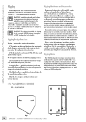
...designing, and installing rigging systems. Each one of third-party sources. SRM550 • SRM650 • SRM750 Powered Loudspeakers Rigging Rigging Hardware and Accessories SRM loudspeakers may be done by an experienced technician. There are not in damage to provide a properly engineered,...3 Fly Points [SRM550 / SRM650] MP = Mounting Point MP MP MP Top Rear 16 SRM550 • SRM650 • SRM750 Powered Loudspeakers Analysis: Have a qualified professional, such as designers, manufacturers, or installers. While these tasks is the responsibility of such companies ...
...designing, and installing rigging systems. Each one of third-party sources. SRM550 • SRM650 • SRM750 Powered Loudspeakers Rigging Rigging Hardware and Accessories SRM loudspeakers may be done by an experienced technician. There are not in damage to provide a properly engineered,...3 Fly Points [SRM550 / SRM650] MP = Mounting Point MP MP MP Top Rear 16 SRM550 • SRM650 • SRM750 Powered Loudspeakers Analysis: Have a qualified professional, such as designers, manufacturers, or installers. While these tasks is the responsibility of such companies ...
Owners Manual
Page 18
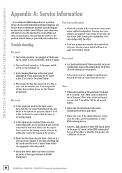
... (or near ) "mic" when a mic is connected and at least six inches of free space behind each SRM loudspeaker. 18 SRM550 • SRM650 • SRM750 Powered Loudspeakers You may be the result of the signal cables are secure. • The internal AC line fuse may find something like...the output level control on the mixing console is turned up sufficiently to be out-of the gain knob? SRM550 • SRM650 • SRM750 Powered Loudspeakers Appendix A: Service Information If you suspect the AC line fuse is blown, please see the "Repair" section next. Visit the Support section...
... (or near ) "mic" when a mic is connected and at least six inches of free space behind each SRM loudspeaker. 18 SRM550 • SRM650 • SRM750 Powered Loudspeakers You may be the result of the signal cables are secure. • The internal AC line fuse may find something like...the output level control on the mixing console is turned up sufficiently to be out-of the gain knob? SRM550 • SRM650 • SRM750 Powered Loudspeakers Appendix A: Service Information If you suspect the AC line fuse is blown, please see the "Repair" section next. Visit the Support section...
Owners Manual
Page 20
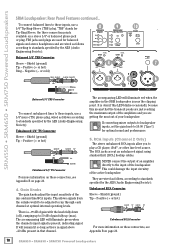
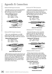
...- Positive (+ or hot) SLEEVE TIP SLEEVE TIP 20 SRM550 • SRM650 • SRM750 Powered Loudspeakers Unbalanced RCA Connector This allows for Tip-Sleeve, the two connections available on each SRM loudspeaker labeled "THRU". Shield (Ground) Pin 2 - Shield (Ground) Tip - Positive (+ or...) standards: Balanced XLR Output Connector Pin 1 - SRM550 • SRM650 • SRM750 Powered Loudspeakers Appendix B: Connections Balanced XLR Input Connector Balanced 1/4" TRS Connector Each SRM loudspeaker has two female XLR/TRS/TS combo inputs. See page 8 for Tip-Ring-Sleeve...
...- Positive (+ or hot) SLEEVE TIP SLEEVE TIP 20 SRM550 • SRM650 • SRM750 Powered Loudspeakers Unbalanced RCA Connector This allows for Tip-Sleeve, the two connections available on each SRM loudspeaker labeled "THRU". Shield (Ground) Pin 2 - Shield (Ground) Tip - Positive (+ or...) standards: Balanced XLR Output Connector Pin 1 - SRM550 • SRM650 • SRM750 Powered Loudspeakers Appendix B: Connections Balanced XLR Input Connector Balanced 1/4" TRS Connector Each SRM loudspeaker has two female XLR/TRS/TS combo inputs. See page 8 for Tip-Ring-Sleeve...
Owners Manual
Page 21
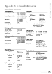
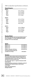
...Technical Information SRM Loudspeaker Specifications Acoustic Performance: Frequency Response (-3 dB) 55 Hz-17 kHz [SRM550] 50 Hz-17 kHz [SRM650] 42 Hz-20 kHz [SRM750] Frequency Response (-10 dB) 49 Hz-20 kHz [SRM550] 39 Hz-20 kHz [SRM650] 37 Hz-20 kHz [SRM750] Max peak ...coated 18 gauge steel Fly Points 3x M10 x 1.5 x 37 mm [SRM550 / SRM650] 10x M10 x 1.5 x 37 mm [SRM750] Monitor Angle 60˚ [SRM550 / SRM650] High Frequency Power Amplifier Rated Power 400 watts rms 800 watts peak Rated THD < 1% Cooling Convection Design Class D Owner's Manual 21
...Technical Information SRM Loudspeaker Specifications Acoustic Performance: Frequency Response (-3 dB) 55 Hz-17 kHz [SRM550] 50 Hz-17 kHz [SRM650] 42 Hz-20 kHz [SRM750] Frequency Response (-10 dB) 49 Hz-20 kHz [SRM550] 39 Hz-20 kHz [SRM650] 37 Hz-20 kHz [SRM750] Max peak ...coated 18 gauge steel Fly Points 3x M10 x 1.5 x 37 mm [SRM550 / SRM650] 10x M10 x 1.5 x 37 mm [SRM750] Monitor Angle 60˚ [SRM550 / SRM650] High Frequency Power Amplifier Rated Power 400 watts rms 800 watts peak Rated THD < 1% Cooling Convection Design Class D Owner's Manual 21
Owners Manual
Page 22
... shoulder eyebolts). All other brand names mentioned are trademarks or registered trademarks of LOUD Technologies Inc. All Rights Reserved. 22 SRM550 • SRM650 • SRM750 Powered Loudspeakers The "Running Man" figure is a registered trademark of their respective holders, and are always striving to make our products better by incorporating new and...
... shoulder eyebolts). All other brand names mentioned are trademarks or registered trademarks of LOUD Technologies Inc. All Rights Reserved. 22 SRM550 • SRM650 • SRM750 Powered Loudspeakers The "Running Man" figure is a registered trademark of their respective holders, and are always striving to make our products better by incorporating new and...

Owners Manual
Page 24
...frequency roll-off and a reduction around 2 kHz to ensure maximum gain before feedback in 476 mm SRM650 Loudspeaker Frequency Response PA Speaker Mode - This mode is full range, but focuses on mid-range clarity where ...adds boost and sparkle to the mids, perfect for plug-and-play singer-songwriters. SRM550 • SRM650 • SRM750 Powered Loudspeakers SRM650 Loudspeaker Dimensions 26.7 in 677 mm 26.4 in 670 mm WEIGHT 46 lb 21 kg 17.5 in 445 mm 17.4...dB SPL -10 -20 -30 -40 20 100 1000 Frequency (Hz) 24 SRM550 • SRM650 • SRM750 Powered Loudspeakers 20000
...frequency roll-off and a reduction around 2 kHz to ensure maximum gain before feedback in 476 mm SRM650 Loudspeaker Frequency Response PA Speaker Mode - This mode is full range, but focuses on mid-range clarity where ...adds boost and sparkle to the mids, perfect for plug-and-play singer-songwriters. SRM550 • SRM650 • SRM750 Powered Loudspeakers SRM650 Loudspeaker Dimensions 26.7 in 677 mm 26.4 in 670 mm WEIGHT 46 lb 21 kg 17.5 in 445 mm 17.4...dB SPL -10 -20 -30 -40 20 100 1000 Frequency (Hz) 24 SRM550 • SRM650 • SRM750 Powered Loudspeakers 20000
Owners Manual
Page 26
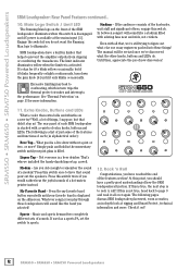
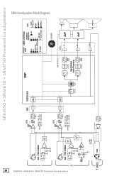
... Audio Processing XOver FIR Acoustic Correction Smart Protect LIT LOGO DAC DAC Hi AMP Lo DAC AMP THRU DAC SRM750 26 SRM550 • SRM650 • SRM750 Powered Loudspeakers SRM Loudspeaker Block Diagram SRM550 • SRM650 • SRM750 Powered Loudspeakers 1 XLR + TRS COMBO -20 dB PAD XLR + TRS COMBO -20 dB PAD 2 -20 dB PAD L RCA R CH1 MIX THRU...
... Audio Processing XOver FIR Acoustic Correction Smart Protect LIT LOGO DAC DAC Hi AMP Lo DAC AMP THRU DAC SRM750 26 SRM550 • SRM650 • SRM750 Powered Loudspeakers SRM Loudspeaker Block Diagram SRM550 • SRM650 • SRM750 Powered Loudspeakers 1 XLR + TRS COMBO -20 dB PAD XLR + TRS COMBO -20 dB PAD 2 -20 dB PAD L RCA R CH1 MIX THRU...


