User Guide
Page 3
...to make changes without notice. Netware® is a registered trademark of AMD Corporation. h Visit the MSI website for further guidance. We take every care in the preparation of this document is given as to...with your place of Novell, Inc. NVIDIA, the NVIDIA logo, DualNet, and nForce are registered trademarks of MICRO-STAR INTERNATIONAL. Revision History Revision V1.1 Revision History Changing nForce2 SPP NB to the correctness of their respective ... Alternatively, please try the following help resources for FAQ, technical guide, BIOS updates, driver updates, and other countries.
...to make changes without notice. Netware® is a registered trademark of AMD Corporation. h Visit the MSI website for further guidance. We take every care in the preparation of this document is given as to...with your place of Novell, Inc. NVIDIA, the NVIDIA logo, DualNet, and nForce are registered trademarks of MICRO-STAR INTERNATIONAL. Revision History Revision V1.1 Revision History Changing nForce2 SPP NB to the correctness of their respective ... Alternatively, please try the following help resources for FAQ, technical guide, BIOS updates, driver updates, and other countries.
User Guide
Page 5
Getting Started 1-1 Mainboard Specifications 1-2 Mainboard Layout 1-4 MSI Special Features 1-5 Fuzzy Logic™ 4 1-5 Live BIOS™/Live Driver 1-6 Live Monitor 1-7 PC Alert™ 4 1-8 Chapter 2. Hardware Setup 2-1 Quick Components Guide 2-2 Central Processing Unit: CPU 2-3 CPU Core Speed Derivation ... 2-7 Introduction to DDR SDRAM 2-7 DIMM Module Combination 2-8 Installing DDR Modules 2-8 Power Supply 2-9 ATX 20-Pin Power Connector: JWR1 2-9 ATX 12V Power Connector: JPW1 2-9 v CONTENTS FCC-B Radio Frequency Interference Statement iii Copyright Notice iii ...
Getting Started 1-1 Mainboard Specifications 1-2 Mainboard Layout 1-4 MSI Special Features 1-5 Fuzzy Logic™ 4 1-5 Live BIOS™/Live Driver 1-6 Live Monitor 1-7 PC Alert™ 4 1-8 Chapter 2. Hardware Setup 2-1 Quick Components Guide 2-2 Central Processing Unit: CPU 2-3 CPU Core Speed Derivation ... 2-7 Introduction to DDR SDRAM 2-7 DIMM Module Combination 2-8 Installing DDR Modules 2-8 Power Supply 2-9 ATX 20-Pin Power Connector: JWR1 2-9 ATX 12V Power Connector: JPW1 2-9 v CONTENTS FCC-B Radio Frequency Interference Statement iii Copyright Notice iii ...
User Guide
Page 13
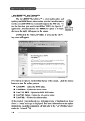
Click the desired button to the "Live Update Guide" under the "Manual" Tab. 1-6 Updates the VGA BIOS online. z ...more information on the update instructions, insert the companion CD and refer to start the update process. MS-6777 M-ATX Mainboard Live BIOS™/Live Driver™ The Live BIOS™/Live Driver™ is displayed. Updates the ... used to detect and update your BIOS/drivers online so that you need to install the "MSI Live Update 2" application. z Live BIOS - After installation, the "MSI Live Update 2" icon (as shown on the right) will appear: Five buttons are placed ...
Click the desired button to the "Live Update Guide" under the "Manual" Tab. 1-6 Updates the VGA BIOS online. z ...more information on the update instructions, insert the companion CD and refer to start the update process. MS-6777 M-ATX Mainboard Live BIOS™/Live Driver™ The Live BIOS™/Live Driver™ is displayed. Updates the ... used to detect and update your BIOS/drivers online so that you need to install the "MSI Live Update 2" application. z Live BIOS - After installation, the "MSI Live Update 2" icon (as shown on the right) will appear: Five buttons are placed ...
User Guide
Page 21
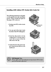
.... 3. You may need a screw drive to fix the cooling fan set . 1. Hardware Setup Installing AMD Athlon CPU (Socket 462) Cooler Set The following instructions will guide you through the heat sink installation process. Please consult your mainboard. Use one end of the clip to dissipate the heat more effectively. 2-5 Apply some... . Connect the fan to the power supply connector provided on top of your CPU cooler set onto the CPU. 2. Please apply some heat sink paste MSI Reminds You... Position your CPU to hook the latch of the clip. 4.
.... 3. You may need a screw drive to fix the cooling fan set . 1. Hardware Setup Installing AMD Athlon CPU (Socket 462) Cooler Set The following instructions will guide you through the heat sink installation process. Please consult your mainboard. Use one end of the clip to dissipate the heat more effectively. 2-5 Apply some... . Connect the fan to the power supply connector provided on top of your CPU cooler set onto the CPU. 2. Please apply some heat sink paste MSI Reminds You... Position your CPU to hook the latch of the clip. 4.
User Guide
Page 34
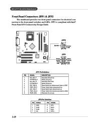
... 7 NC PIN SIGNAL 2 SPK- 4 BUZ+ 6 BUZ- 8 SPK+ Do not use. MS-6777 M-ATX Mainboard Front Panel Connectors: JFP1 & JFP2 The mainboard provides two front panel connectors for electrical connection to GND Reserved. JFP1 is compliant with Intel® Front Panel I/O Connectivity Design Guide. 2-18 Speaker JFP2 8 7 Power LED 21 JFP1 10 Power Switch Power...
... 7 NC PIN SIGNAL 2 SPK- 4 BUZ+ 6 BUZ- 8 SPK+ Do not use. MS-6777 M-ATX Mainboard Front Panel Connectors: JFP1 & JFP2 The mainboard provides two front panel connectors for electrical connection to GND Reserved. JFP1 is compliant with Intel® Front Panel I/O Connectivity Design Guide. 2-18 Speaker JFP2 8 7 Power LED 21 JFP1 10 Power Switch Power...

User Guide
Page 35
... to be jumpered in order to have signal output directed to the front panel audio and is compliant with Intel® Front Panel I/O Connectivity Design Guide. Otherwise, the Line-Out connector on the back panel will not function. 6 10 59 2-19 If you to connect to the rear audio ports. JAUD1... to control headphone amplifier 8 KEY No pin 9 AUD_FPOUT_L Left channel audio signal to front panel 10 AUD_RET_L Left channel audio signal return from front panel MSI Reminds You...
... to be jumpered in order to have signal output directed to the front panel audio and is compliant with Intel® Front Panel I/O Connectivity Design Guide. Otherwise, the Line-Out connector on the back panel will not function. 6 10 59 2-19 If you to connect to the rear audio ports. JAUD1... to control headphone amplifier 8 KEY No pin 9 AUD_FPOUT_L Left channel audio signal to front panel 10 AUD_RET_L Left channel audio signal return from front panel MSI Reminds You...
User Guide
Page 36
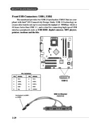
... peripherals such as USB HDD, digital cameras, MP3 players, printers, modems and the like. MS-6777 M-ATX Mainboard Front USB Connectors: USB1, USB2 The mainboard provides two USB 2.0 pin headers USB1/2 that are compliant with Intel® I/O Connectivity Design Guide. USB 2.0 technology increases data transfer rate up to USB1 or USB2 2 10 1 9 USB1/2 USB...
... peripherals such as USB HDD, digital cameras, MP3 players, printers, modems and the like. MS-6777 M-ATX Mainboard Front USB Connectors: USB1, USB2 The mainboard provides two USB 2.0 pin headers USB1/2 that are compliant with Intel® I/O Connectivity Design Guide. USB 2.0 technology increases data transfer rate up to USB1 or USB2 2 10 1 9 USB1/2 USB...
User Guide
Page 53
Settings: 6, 8, 10, 12, 15, 20, 24 and 30. Due to compliance with PC2001 design guide, the system is able to select the MPS version supported by your operating system. Settings: Enabled and Disabled. You need to run in APIC mode. ... This field allows you to select which MPS (Multi-Processor Specification) version to be used to enable or disable the APIC (Advanced Programmable Interrupt Controller). MS-6777 M-ATX Mainboard Typematic Rate (Chars/Sec) After Typematic Rate Setting is enabled, this item allows you to set the rate (characters/second) at which version to...
Settings: 6, 8, 10, 12, 15, 20, 24 and 30. Due to compliance with PC2001 design guide, the system is able to select the MPS version supported by your operating system. Settings: Enabled and Disabled. You need to run in APIC mode. ... This field allows you to select which MPS (Multi-Processor Specification) version to be used to enable or disable the APIC (Advanced Programmable Interrupt Controller). MS-6777 M-ATX Mainboard Typematic Rate (Chars/Sec) After Typematic Rate Setting is enabled, this item allows you to set the rate (characters/second) at which version to...
