User Guide
Page 6
... (optional 2-12 VGA Connector 2-12 Serial Port Connectors: COM A & COM 2 2-13 Parallel Port Connector 2-14 Joystick/Midi Connector 2-15 Audio Port Connectors 2-15 Connectors 2-16 Floppy Disk Drive Connector: FDD1 2-16 Hard Disk Connectors: IDE1 & IDE2 2-17 Fan Power Connectors: CPUFAN1.../SYS_FAN1 2-18 Front Panel Audio Connector: JAUD1 2-19 Front Panel Connectors: JFP1 & JFP2 2-20 S-Bracket Connector: JSP1 2-21 Front USB Connectors: JUSB1 & JUSB2 2-22 D-...
... (optional 2-12 VGA Connector 2-12 Serial Port Connectors: COM A & COM 2 2-13 Parallel Port Connector 2-14 Joystick/Midi Connector 2-15 Audio Port Connectors 2-15 Connectors 2-16 Floppy Disk Drive Connector: FDD1 2-16 Hard Disk Connectors: IDE1 & IDE2 2-17 Fan Power Connectors: CPUFAN1.../SYS_FAN1 2-18 Front Panel Audio Connector: JAUD1 2-19 Front Panel Connectors: JFP1 & JFP2 2-20 S-Bracket Connector: JSP1 2-21 Front USB Connectors: JUSB1 & JUSB2 2-22 D-...
User Guide
Page 7
or 6-Channel Audio Function A-1 Installing the Audio Driver A-2 Using 4- or 6-Channel Audio Function A-4 Testing the Connected Speakers A-14 Playing KaraOK A-15 Troubleshooting T-1 Glossary ...G-1 vii Entering Setup 3-2 Selecting the First Boot Device 3-2 Control Keys 3-3 Getting Help 3-3 The Main ...
or 6-Channel Audio Function A-1 Installing the Audio Driver A-2 Using 4- or 6-Channel Audio Function A-4 Testing the Connected Speakers A-14 Playing KaraOK A-15 Troubleshooting T-1 Glossary ...G-1 vii Entering Setup 3-2 Selecting the First Boot Device 3-2 Control Keys 3-3 Getting Help 3-3 The Main ...
User Guide
Page 10
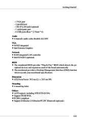
... Management Interface (DMI) function which detects the pe- Getting Started - 1 VGA port - 1 parallel port - 1 RJ-45 LAN jack (optional) - 1 audio/game port - 6 USB ports (Rear * 2/ Front * 4) Audio h 6 channels audio codec Realtek ALC650 VGA h 845GE integrated h Intel Extreme Graphics Network h ICH4 integrated LAN controller h Intel 82562ET (optional) BIOS h The mainboard BIOS provides "Plug & Play" BIOS...
... Management Interface (DMI) function which detects the pe- Getting Started - 1 VGA port - 1 parallel port - 1 RJ-45 LAN jack (optional) - 1 audio/game port - 6 USB ports (Rear * 2/ Front * 4) Audio h 6 channels audio codec Realtek ALC650 VGA h 845GE integrated h Intel Extreme Graphics Network h ICH4 integrated LAN controller h Intel 82562ET (optional) BIOS h The mainboard BIOS provides "Plug & Play" BIOS...
User Guide
Page 18
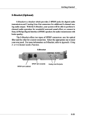
...Bracket offers two types of SPDIF connectors: one to meet your system will be able to perform 6channel audio operation for audio transmission with better quality. Using 4- or 6-Channel Audio Function. S-Bracket CEN/SUB RL/RR SPDIF jack (coaxial) SPDIF jack (optical) Analog Line-Out ...jacks 1-11 Getting Started S-Bracket (Optional) S-Bracket is a bracket which provides 2 SPDIF jacks for digital audio transmission and 2 analog Line-Out connectors for coaxial connection. For more information on S-Bracket, refer to Sony & Philips Digital Interface (SPDIF...
...Bracket offers two types of SPDIF connectors: one to meet your system will be able to perform 6channel audio operation for audio transmission with better quality. Using 4- or 6-Channel Audio Function. S-Bracket CEN/SUB RL/RR SPDIF jack (coaxial) SPDIF jack (optical) Analog Line-Out ...jacks 1-11 Getting Started S-Bracket (Optional) S-Bracket is a bracket which provides 2 SPDIF jacks for digital audio transmission and 2 analog Line-Out connectors for coaxial connection. For more information on S-Bracket, refer to Sony & Philips Digital Interface (SPDIF...
User Guide
Page 19
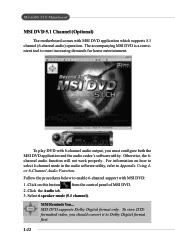
... on how to select 6-channel mode in the audio software utility, refer to enable 6-channel support with MSI DVD application which supports 5.1 channel (6-channel audio) operation. Using 4or 6-Channel Audio Function. MS-6580 ATX Mainboard MSI DVD 5.1 Channel (Optional) The motherboard comes with MSI DVD: 1. Click the Audio tab. 3. Otherwise, the 6channel audio function will not work properly. Select 6 speaker mode...
... on how to select 6-channel mode in the audio software utility, refer to enable 6-channel support with MSI DVD application which supports 5.1 channel (6-channel audio) operation. Using 4or 6-Channel Audio Function. MS-6580 ATX Mainboard MSI DVD 5.1 Channel (Optional) The motherboard comes with MSI DVD: 1. Click the Audio tab. 3. Otherwise, the 6channel audio function will not work properly. Select 6 speaker mode...
User Guide
Page 35
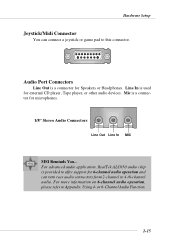
... Line Out is a connector for Speakers or Headphones. or 6-Channel Audio Function. 2-15 Mic is a connector for microphones. 1/8" Stereo Audio Connectors Line Out Line In MIC MSI Reminds You... Hardware Setup Joystick/Midi Connector You can turn rear audio connectors from 2-channel to 4-/6-channel audio. Line In is provided to offer support for external CD...
... Line Out is a connector for Speakers or Headphones. or 6-Channel Audio Function. 2-15 Mic is a connector for microphones. 1/8" Stereo Audio Connectors Line Out Line In MIC MSI Reminds You... Hardware Setup Joystick/Midi Connector You can turn rear audio connectors from 2-channel to 4-/6-channel audio. Line In is provided to offer support for external CD...
User Guide
Page 39
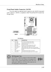
... to have signal output directed to the JAUD1 front panel audio connector. Hardware Setup Front Panel Audio Connector: JAUD1 You can connect an optional audio connector to the rear audio ports. JAUD1 is compliant to Intel® Front Panel ...audio circuits 5 AUD_FPOUT_R Right channel audio signal to front panel 6 AUD_RET_R Right channel audio signal return from front panel 7 HP_ON Reserved for future use to control headphone amplifier 8 KEY No pin 9 AUD_FPOUT_L Left channel audio signal to front panel 10 AUD_RET_L Left channel audio signal return from front panel MSI...
... to have signal output directed to the JAUD1 front panel audio connector. Hardware Setup Front Panel Audio Connector: JAUD1 You can connect an optional audio connector to the rear audio ports. JAUD1 is compliant to Intel® Front Panel ...audio circuits 5 AUD_FPOUT_R Right channel audio signal to front panel 6 AUD_RET_R Right channel audio signal return from front panel 7 HP_ON Reserved for future use to control headphone amplifier 8 KEY No pin 9 AUD_FPOUT_L Left channel audio signal to front panel 10 AUD_RET_L Left channel audio signal return from front panel MSI...
User Guide
Page 41
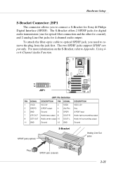
... the S-Bracket, refer to Appendix. To attach the fiber-optic cable to optical SPDIF jack, you to connect a S-Bracket for 4-channel audio output. Hardware Setup S-Bracket Connector: JSP1 The connector allows you need to remove the plug from the jack first. The two SPDIF jacks support... SPDIF output only. Using 4or 6-Channel Audio Function. 11 1 12 2 JSP1 JSP1 Pin Definition PIN SIGNAL DESCRIPTION PIN SIGNAL 1 VCC5 VCC 5V 2 VDD3 3 SPDFO S/PDIF output 4 (No Pin) 5 ...
... the S-Bracket, refer to Appendix. To attach the fiber-optic cable to optical SPDIF jack, you to connect a S-Bracket for 4-channel audio output. Hardware Setup S-Bracket Connector: JSP1 The connector allows you need to remove the plug from the jack first. The two SPDIF jacks support... SPDIF output only. Using 4or 6-Channel Audio Function. 11 1 12 2 JSP1 JSP1 Pin Definition PIN SIGNAL DESCRIPTION PIN SIGNAL 1 VCC5 VCC 5V 2 VDD3 3 SPDFO S/PDIF output 4 (No Pin) 5 ...
User Guide
Page 46
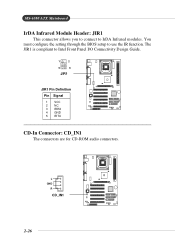
The JIR1 is compliant to use the IR function. You must configure the setting through the BIOS setup to Intel Front Panel I/O Connectivity Design Guide. 1 2 5 6 JIR1 JIR1 Pin Definition Pin Signal 1 VCC 2 NC 3 IRRX 4 GND 5 IRTX CD-In Connector: CD_IN1 The connectors are for CD-ROM audio connectors. L GND R CD_IN1 2-26 MS-6580 ATX Mainboard IrDA Infrared Module Header: JIR1 This connector allows you to connect to IrDA Infrared modules.
The JIR1 is compliant to use the IR function. You must configure the setting through the BIOS setup to Intel Front Panel I/O Connectivity Design Guide. 1 2 5 6 JIR1 JIR1 Pin Definition Pin Signal 1 VCC 2 NC 3 IRRX 4 GND 5 IRTX CD-In Connector: CD_IN1 The connectors are for CD-ROM audio connectors. L GND R CD_IN1 2-26 MS-6580 ATX Mainboard IrDA Infrared Module Header: JIR1 This connector allows you to connect to IrDA Infrared modules.
User Guide
Page 49
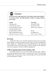
... to meet your needs. Hardware Setup Attention! When adding or removing expansion cards, make any necessary hardware or software settings for ATX family motherboards. CNR is a specially designed network, audio, or modem riser card for the expansion card, such as jumpers, switches or BIOS configuration. Meanwhile, read the documentation for the expansion...
... to meet your needs. Hardware Setup Attention! When adding or removing expansion cards, make any necessary hardware or software settings for ATX family motherboards. CNR is a specially designed network, audio, or modem riser card for the expansion card, such as jumpers, switches or BIOS configuration. Meanwhile, read the documentation for the expansion...
User Guide
Page 74
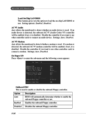
... allows the mainboard to detect whether a modem is disabled. If an audio device is used. AC'97 Modem Auto allows the mainboard to detect whether an audio device is detected, the onboard AC'97 (Audio Codec'97) controller will be enabled; Disable the controller if you want ...Set Super I/O Press to connect an audio device. Settings: Auto, Disabled. Setting options: Enabled, Disabled. Disable the controller if you want to use other controller cards to enter the sub-menu and the following screen appears: OnBoard FDC This is disabled. MS-6580 ATX Mainboard Load OnChip LAN BIOS This...
... allows the mainboard to detect whether a modem is disabled. If an audio device is used. AC'97 Modem Auto allows the mainboard to detect whether an audio device is detected, the onboard AC'97 (Audio Codec'97) controller will be enabled; Disable the controller if you want ...Set Super I/O Press to connect an audio device. Settings: Auto, Disabled. Setting options: Enabled, Disabled. Disable the controller if you want to use other controller cards to enter the sub-menu and the following screen appears: OnBoard FDC This is disabled. MS-6580 ATX Mainboard Load OnChip LAN BIOS This...

User Guide
Page 82
ALC650 allows the board to install and use 4-/6-channel audio function on the board. TOPICS Installing the Audio Driver A-2 Using 4-/6-Channel Audio Function A-4 Testing the Connected Speakers A-14 Playing KaraOK A-15 A-1 or 6-Channel Audio Function The motherboard is equipped with Realtek ALC650 chip, which provides support for better surround sound effect. or 6-Channel Audio Function Appendix: Using 4- The section will tell you how to attach 4 or 6 speakers for 6-channel audio output, including 2 Front, 2 Rear, 1 Center and 1 Subwoofer channel. Using 4-
ALC650 allows the board to install and use 4-/6-channel audio function on the board. TOPICS Installing the Audio Driver A-2 Using 4-/6-Channel Audio Function A-4 Testing the Connected Speakers A-14 Playing KaraOK A-15 A-1 or 6-Channel Audio Function The motherboard is equipped with Realtek ALC650 chip, which provides support for better surround sound effect. or 6-Channel Audio Function Appendix: Using 4- The section will tell you how to attach 4 or 6 speakers for 6-channel audio output, including 2 Front, 2 Rear, 1 Center and 1 Subwoofer channel. Using 4-

User Guide
Page 83
...; XP environment and could look slightly different if you can get access to 4-/6-channel audio operations. Click Next to start installing files into the CD-ROM drive. Click Avance ALC650 Sound Drivers. MS-6580 ATX Mainboard Installing the Audio Driver You need to install the driver for Windows 98SE/ME/2000/XP For Windows...
...; XP environment and could look slightly different if you can get access to 4-/6-channel audio operations. Click Next to start installing files into the CD-ROM drive. Click Avance ALC650 Sound Drivers. MS-6580 ATX Mainboard Installing the Audio Driver You need to install the driver for Windows 98SE/ME/2000/XP For Windows...
User Guide
Page 84
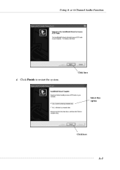
Click here Select this option Click here A-3 or 6-Channel Audio Function 4. Using 4- Click Finish to restart the system.
Click here Select this option Click here A-3 or 6-Channel Audio Function 4. Using 4- Click Finish to restart the system.
User Guide
Page 85
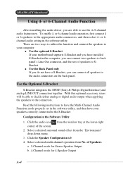
... the S-Bracket: Configuration in the software utility, and then have a S-Bracket, you have installed S-Bracket in the software utility. Click the audio icon from No. MS-6580 ATX Mainboard Using 4- With this optional accessory, users will be able to decide either analog or digital...Channel mode for Stereo-Speaker Output b. 4-Channel mode for 4-Speaker Output A-4 There are able to the audio connectors on the back panel. Use the Back Panel only If you do not have your motherboard supports S-Bracket and you can connect two speakers to back panel's Line-Out connector, and the rest...
... the S-Bracket: Configuration in the software utility, and then have a S-Bracket, you have installed S-Bracket in the software utility. Click the audio icon from No. MS-6580 ATX Mainboard Using 4- With this optional accessory, users will be able to decide either analog or digital...Channel mode for Stereo-Speaker Output b. 4-Channel mode for 4-Speaker Output A-4 There are able to the audio connectors on the back panel. Use the Back Panel only If you do not have your motherboard supports S-Bracket and you can connect two speakers to back panel's Line-Out connector, and the rest...
User Guide
Page 86
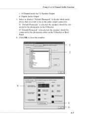
If "Default Phonejack" is deselected, the speakers should be connected to the phonejacks on the S-Bracket or Back Panel. 6. Click OK to use as the audio output connectors. Digital Audio Output 5. or 6-Channel Audio Function c. 6-Channel mode for 5.1-Speaker Output d. Select or deselect "Default Phonejack" to decide which audio device that you wish to close this window. A-5 If "Default Phonejack" is selected, the speakers should be connected to the phonejacks either on the S-Bracket. Using 4-
If "Default Phonejack" is deselected, the speakers should be connected to the phonejacks on the S-Bracket or Back Panel. 6. Click OK to use as the audio output connectors. Digital Audio Output 5. or 6-Channel Audio Function c. 6-Channel mode for 5.1-Speaker Output d. Select or deselect "Default Phonejack" to decide which audio device that you wish to close this window. A-5 If "Default Phonejack" is selected, the speakers should be connected to the phonejacks either on the S-Bracket. Using 4-
User Guide
Page 87
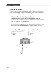
... speakers to the following diagram and caption for Stereo-Speaker Output When this mode is selected, it is selected. MS-6580 ATX Mainboard Connecting the Speakers When you have set the Multi-Channel Audio Function mode properly in the software utility, connect your speakers to the correct phonejacks in accordance with the setting...
... speakers to the following diagram and caption for Stereo-Speaker Output When this mode is selected, it is selected. MS-6580 ATX Mainboard Connecting the Speakers When you have set the Multi-Channel Audio Function mode properly in the software utility, connect your speakers to the correct phonejacks in accordance with the setting...
User Guide
Page 88
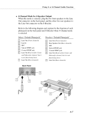
or 6-Channel Audio Function 4-Channel Mode for the function of each phonejack on the S-Bracket. Select "Default Phonejack" 1 Line Out (Front channels) 2 Line In 3 MIC 4 Optical SPDIF jack 5 ...
or 6-Channel Audio Function 4-Channel Mode for the function of each phonejack on the S-Bracket. Select "Default Phonejack" 1 Line Out (Front channels) 2 Line In 3 MIC 4 Optical SPDIF jack 5 ...
User Guide
Page 89
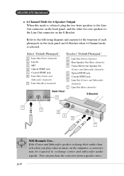
MS-6580 ATX Mainboard 6-Channel Mode for the function of each phonejack on the back panel ...Speaker Output When this mode is selected. If the Center and Subwoofer speaker exchange their audio channels when you play video or music on the S-Bracket. Refer to exchange center and subwoofer audio signals. Select "Default Phonejack" Deselect "Default Phonejack" 1 Line Out (Front channels... SPDIF jack 6 Line Out (Center and Subwoofer channels) 7 Line Out (Rear channels) Back Panel 3 S-Bracket 1 2 4 5 6 7 MSI Reminds You... You can purchase the converter from a speaker store A-8
MS-6580 ATX Mainboard 6-Channel Mode for the function of each phonejack on the back panel ...Speaker Output When this mode is selected. If the Center and Subwoofer speaker exchange their audio channels when you play video or music on the S-Bracket. Refer to exchange center and subwoofer audio signals. Select "Default Phonejack" Deselect "Default Phonejack" 1 Line Out (Front channels... SPDIF jack 6 Line Out (Center and Subwoofer channels) 7 Line Out (Rear channels) Back Panel 3 S-Bracket 1 2 4 5 6 7 MSI Reminds You... You can purchase the converter from a speaker store A-8
User Guide
Page 90
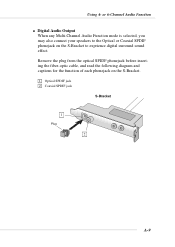
Using 4- Remove the plug from the optical SPIDF phonejack before inserting the fiber-optic cable, and read the following diagram and captions for the function of each phonejack on the S-Bracket to the Optical or Coaxial SPDIF phonejack on the S-Bracket. 1 Optical SPDIF jack 2 Coaxial SPDIF jack S-Bracket 1 Plug 2 A-9 or 6-Channel Audio Function Digital Audio Output When any Multi-Channel Audio Function mode is selected, you may also connect your speakers to exprience digital surround sound effect.
Using 4- Remove the plug from the optical SPIDF phonejack before inserting the fiber-optic cable, and read the following diagram and captions for the function of each phonejack on the S-Bracket to the Optical or Coaxial SPDIF phonejack on the S-Bracket. 1 Optical SPDIF jack 2 Coaxial SPDIF jack S-Bracket 1 Plug 2 A-9 or 6-Channel Audio Function Digital Audio Output When any Multi-Channel Audio Function mode is selected, you may also connect your speakers to exprience digital surround sound effect.
