User Guide
Page 7
... A-15 Troubleshooting T-1 Glossary ...G-1 vii Entering Setup 3-2 Selecting the First Boot Device 3-2 Control Keys 3-3 Getting Help 3-3 The Main Menu 3-4 Standard CMOS Features 3-6 Advanced BIOS Features 3-8 Advanced Chipset Features 3-13 Power Management Features 3-16 PNP/PCI Configurations 3-20 Integrated Peripherals 3-23 PC Health Status 3-27 Frequency/Voltage Control 3-28 Set Supervisor/User Password...
... A-15 Troubleshooting T-1 Glossary ...G-1 vii Entering Setup 3-2 Selecting the First Boot Device 3-2 Control Keys 3-3 Getting Help 3-3 The Main Menu 3-4 Standard CMOS Features 3-6 Advanced BIOS Features 3-8 Advanced Chipset Features 3-13 Power Management Features 3-16 PNP/PCI Configurations 3-20 Integrated Peripherals 3-23 PC Health Status 3-27 Frequency/Voltage Control 3-28 Set Supervisor/User Password...
User Guide
Page 8
Designed to fit the advanced Intel® Pentium 4/Celeron processor in the 478-pin package, the 845GE Max mainboard delivers a high performance and professional desktop platform solution. 1-1 Getting Started Chapter 1. The 845GE Max mainboard is based on Intel® 845GE & ICH4 chipsets for purchasing the 845GE Max (MS-6580 v2.X) ATX mainboard. Getting Started Getting Started Thank you for optimal system efficiency.
Designed to fit the advanced Intel® Pentium 4/Celeron processor in the 478-pin package, the 845GE Max mainboard delivers a high performance and professional desktop platform solution. 1-1 Getting Started Chapter 1. The 845GE Max mainboard is based on Intel® 845GE & ICH4 chipsets for purchasing the 845GE Max (MS-6580 v2.X) ATX mainboard. Getting Started Getting Started Thank you for optimal system efficiency.
User Guide
Page 9
..., Bus Master and Ultra ATA66/100 operation modes h Can connect up to 2.8 GHz and up* (*not tested yet) Chipsets h Intel® 845GE chipsets - Support 400/533 MHz Intel NetBurst micro-architecture bus h Intel® ICH4 chipset - MS-6580 ATX Mainboard Mainboard Specifications CPU h Supports Socket 478 for Intel® Pentium 4/Celeron processors h Core Frequency from 1.4 GHz... with 360K, 720K, 1.2M, 1.44M and 2.88Mbytes - 2 serial ports COM A & COM 2 1-2 Integrated LAN controller Main Memory h Supports two 184-pin DDR200/DDR266/DDR333 DIMMs h Supports Max.
..., Bus Master and Ultra ATA66/100 operation modes h Can connect up to 2.8 GHz and up* (*not tested yet) Chipsets h Intel® 845GE chipsets - Support 400/533 MHz Intel NetBurst micro-architecture bus h Intel® ICH4 chipset - MS-6580 ATX Mainboard Mainboard Specifications CPU h Supports Socket 478 for Intel® Pentium 4/Celeron processors h Core Frequency from 1.4 GHz... with 360K, 720K, 1.2M, 1.44M and 2.88Mbytes - 2 serial ports COM A & COM 2 1-2 Integrated LAN controller Main Memory h Supports two 184-pin DDR200/DDR266/DDR333 DIMMs h Supports Max.
User Guide
Page 11
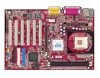
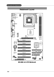
MS-6580 ATX Mainboard Mainboard Layout Top : mouse Bottom: keyboard JPW1 T:LAN jack (optional) B:USB ports CPUFAN1 ATX Power Supply Top : Game port Bottom: Line-Out Line-In Mic Intel 845GE chipset AGP Slot BIOS DDR 1 DDR 2 JIR1 W i n b o nd W 8 36 2 7 H F- A W CD_IN1 Codec PCI Slot 1 PCI Slot 2 PCI Slot 3 PCI Slot 4 PCI Slot 5 ICH 4 BATT + IDE 1 JBAT1 IDE 2 SYS_FAN1 JSP1 JAUD1 JDB1 PCI Slot 6 CNR FDD1 JUSB1 JUSB2 JBT1 MS-6580 v2.X ATX Mainboard JFP2 JFP1 1-4
MS-6580 ATX Mainboard Mainboard Layout Top : mouse Bottom: keyboard JPW1 T:LAN jack (optional) B:USB ports CPUFAN1 ATX Power Supply Top : Game port Bottom: Line-Out Line-In Mic Intel 845GE chipset AGP Slot BIOS DDR 1 DDR 2 JIR1 W i n b o nd W 8 36 2 7 H F- A W CD_IN1 Codec PCI Slot 1 PCI Slot 2 PCI Slot 3 PCI Slot 4 PCI Slot 5 ICH 4 BATT + IDE 1 JBAT1 IDE 2 SYS_FAN1 JSP1 JAUD1 JDB1 PCI Slot 6 CNR FDD1 JUSB1 JUSB2 JBT1 MS-6580 v2.X ATX Mainboard JFP2 JFP1 1-4
User Guide
Page 12
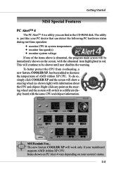
... above is abnormal, the program main screen will be shown until user disables the warning. MSI Reminds You... The new feature COOLER XP will continue to a different display board with information about the CPU and chipset. The utility is a utility you can detect the following PC hardware status during real time...on PC Alert 4 vary depending on the steering wheel and the system will show a steering wheel (as shown right) with the same CPU and chipset information. Right-click any point on your PC doctor that can find in red. To do so, simply click COOLER XP and the screen will...
... above is abnormal, the program main screen will be shown until user disables the warning. MSI Reminds You... The new feature COOLER XP will continue to a different display board with information about the CPU and chipset. The utility is a utility you can detect the following PC hardware status during real time...on PC Alert 4 vary depending on the steering wheel and the system will show a steering wheel (as shown right) with the same CPU and chipset information. Right-click any point on your PC doctor that can find in red. To do so, simply click COOLER XP and the screen will...
User Guide
Page 15
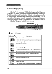
... properly. This will start writing VGA sign-on message to help users understand their system. This special feature is damaged or not installed properly. MS-6580 ATX Mainboard D-Bracket™ 2 (Optional) D-Bracket™ 2 is an external USB bracket integrating four Diagnostic LEDs, which use the feature ...useful for fast booting. Decompressing BIOS image to detect if there are any problems or failures. Initializing Keyboard Controller. Early Chipset Initialization Memory Detection Test - The LEDs provide up to 16 combinations of signals to debug the system.
... properly. This will start writing VGA sign-on message to help users understand their system. This special feature is damaged or not installed properly. MS-6580 ATX Mainboard D-Bracket™ 2 (Optional) D-Bracket™ 2 is an external USB bracket integrating four Diagnostic LEDs, which use the feature ...useful for fast booting. Decompressing BIOS image to detect if there are any problems or failures. Initializing Keyboard Controller. Early Chipset Initialization Memory Detection Test - The LEDs provide up to 16 combinations of signals to debug the system.
User Guide
Page 38
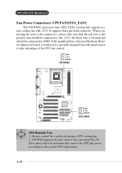
... is Ground and should be connected to GND. GND +12V SENSOR CPUFAN1 GND +12V SENSOR SYS_FAN1 MSI Reminds You... 1. If the mainboard has a System Hardware Monitor chipset on-board, you must use a specially designed fan with +12V. MS-6580 ATX Mainboard Fan Power Connectors: CPUFAN1/SYS_FAN1 The CPUFAN1 (processor fan), SYS_FAN1 (system fan) support...
... is Ground and should be connected to GND. GND +12V SENSOR CPUFAN1 GND +12V SENSOR SYS_FAN1 MSI Reminds You... 1. If the mainboard has a System Hardware Monitor chipset on-board, you must use a specially designed fan with +12V. MS-6580 ATX Mainboard Fan Power Connectors: CPUFAN1/SYS_FAN1 The CPUFAN1 (processor fan), SYS_FAN1 (system fan) support...
User Guide
Page 49
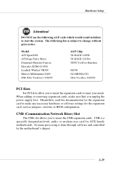
..., make any necessary hardware or software settings for the expansion card, such as jumpers, switches or BIOS configuration. Meanwhile, read the documentation for ATX family motherboards. CNR is done through software and controlled by the motherboard's chipset. 2-29
..., make any necessary hardware or software settings for the expansion card, such as jumpers, switches or BIOS configuration. Meanwhile, read the documentation for ATX family motherboards. CNR is done through software and controlled by the motherboard's chipset. 2-29
User Guide
Page 54
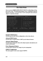
... CMOS Features Use this menu to change the values in the chipset registers and optimize your system supports PnP/PCI. 3-4 Power Management Features Use this menu to setup the items of AMI® special enhanced features. MS-6580 ATX Mainboard The Main Menu Once you enter AMIBIOS NEW SETUP UTILITY..., the Main Menu will appear on the screen. Advanced Chipset Features Use this menu to enter the sub-menu. Advanced BIOS Features Use...
... CMOS Features Use this menu to change the values in the chipset registers and optimize your system supports PnP/PCI. 3-4 Power Management Features Use this menu to setup the items of AMI® special enhanced features. MS-6580 ATX Mainboard The Main Menu Once you enter AMIBIOS NEW SETUP UTILITY..., the Main Menu will appear on the screen. Advanced Chipset Features Use this menu to enter the sub-menu. Advanced BIOS Features Use...
User Guide
Page 61
... in cache. Hyper Threading Function This field is possible if you cannot run the OS/2® operating system with HT Technology; *Chipset: An Intel® Chipset that supports HT Technology; *BIOS: A BIOS that supports HT Technology. When the CPU requests data, the system transfers the requested...Processor with DRAM larger than 64MB. and *OS: An operating system that supports HT Technology and has it is used for the operating system. MSI Reminds You... Setting options: Disabled, WriteBack, WriteThru. BIOS Setup Boot To OS/2 for DRAM > 64MB This allows you to run the OS...
... in cache. Hyper Threading Function This field is possible if you cannot run the OS/2® operating system with HT Technology; *Chipset: An Intel® Chipset that supports HT Technology; *BIOS: A BIOS that supports HT Technology. When the CPU requests data, the system transfers the requested...Processor with DRAM larger than 64MB. and *OS: An operating system that supports HT Technology and has it is used for the operating system. MSI Reminds You... Setting options: Disabled, WriteBack, WriteThru. BIOS Setup Boot To OS/2 for DRAM > 64MB This allows you to run the OS...
User Guide
Page 63
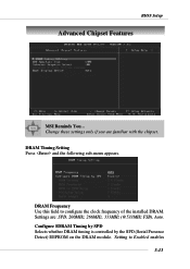
Settings are familiar with the chipset. Setting to configure the clock frequency of the installed DRAM. DRAM Timing Setting Press and the following sub-menu appears. Configure SDRAM Timing by SPD Selects whether DRAM timing is controlled by the SPD (Serial Presence Detect) EEPROM on the DRAM module. DRAM Frequency Use this field to Enabled enables 3-13 BIOS Setup Advanced Chipset Features MSI Reminds You... Change these settings only if you are : SPD, 200MHz, 266MHz, 333MHz (@533MHz FSB), Auto.
Settings are familiar with the chipset. Setting to configure the clock frequency of the installed DRAM. DRAM Timing Setting Press and the following sub-menu appears. Configure SDRAM Timing by SPD Selects whether DRAM timing is controlled by the SPD (Serial Presence Detect) EEPROM on the DRAM module. DRAM Frequency Use this field to Enabled enables 3-13 BIOS Setup Advanced Chipset Features MSI Reminds You... Change these settings only if you are : SPD, 200MHz, 266MHz, 333MHz (@533MHz FSB), Auto.
User Guide
Page 66
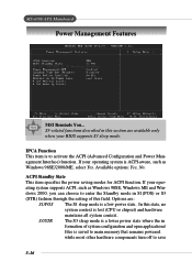
... item specifies the power saving modes for ACPI function. In this section are : S1/POS The S1 sleep mode is lost (CPU or chipset) and hardware maintains all system context. Options are available only when your BIOS supports S3 sleep mode. MS-6580 ATX Mainboard Power Management Features MSI Reminds You... If your oper-
... item specifies the power saving modes for ACPI function. In this section are : S1/POS The S1 sleep mode is lost (CPU or chipset) and hardware maintains all system context. Options are available only when your BIOS supports S3 sleep mode. MS-6580 ATX Mainboard Power Management Features MSI Reminds You... If your oper-

User Guide
Page 100
... to BIOS maker as A = AMI(R) W = AWARD(R) P = PHOENIX (R). 2nd digit refers to the internal chipset code. 3rd digit refers to the date this BIOS is the BIOS version. Customer-specific request When we release a new... = 486, 7 = 586, 8 = 686. 4th digit is incremental. 091096 refers to the processor class as MS = all standard customers. A word of advice, though, do not upgrade to the new BIOS, unless you really ... BIOS will be worth it. V1.0 refers to the BIOS version. 091096 refers to http://www.msi.com.tw/support/bios/note.htm for the release. T-3 A: Please refer to the date this ...
... to BIOS maker as A = AMI(R) W = AWARD(R) P = PHOENIX (R). 2nd digit refers to the internal chipset code. 3rd digit refers to the date this BIOS is the BIOS version. Customer-specific request When we release a new... = 486, 7 = 586, 8 = 686. 4th digit is incremental. 091096 refers to the processor class as MS = all standard customers. A word of advice, though, do not upgrade to the new BIOS, unless you really ... BIOS will be worth it. V1.0 refers to the BIOS version. 091096 refers to http://www.msi.com.tw/support/bios/note.htm for the release. T-3 A: Please refer to the date this ...
User Guide
Page 103
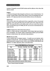
... the primary circuits for transmitting and receiving data; For personal computers, clock cycles generally refer to represent a bit. For example, a modem chipset contains all subsystems. Clock Cycle Clock cycle (or tick) is a widely used in a single clock tick. CMOS (Complementary Metal-Oxide Semiconductor...(up to perform one transistor and a capacitor to the main system clock, which features high speed and low power consumption. MS-6580 ATX Mainboard contents of frequently accessed RAM locations and the addresses where these data items are 66 million clock cycles per second....
... the primary circuits for transmitting and receiving data; For personal computers, clock cycles generally refer to represent a bit. For example, a modem chipset contains all subsystems. Clock Cycle Clock cycle (or tick) is a widely used in a single clock tick. CMOS (Complementary Metal-Oxide Semiconductor...(up to perform one transistor and a capacitor to the main system clock, which features high speed and low power consumption. MS-6580 ATX Mainboard contents of frequently accessed RAM locations and the addresses where these data items are 66 million clock cycles per second....