User Guide
Page 7
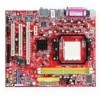
... processor, the K9N6GM series delivers a high performance and professional desktop platform solution. The K9N6GM series is design based on MCP(P)61 / MCP(S)61 / MCP(V)61 chipset for choosing the K9N6GM series (MS-7309 v1.x) Micro-ATX mainboard.
... processor, the K9N6GM series delivers a high performance and professional desktop platform solution. The K9N6GM series is design based on MCP(P)61 / MCP(S)61 / MCP(V)61 chipset for choosing the K9N6GM series (MS-7309 v1.x) Micro-ATX mainboard.
User Guide
Page 8
...64 and Athlon 64 X2 (For the latest information about CPU, please visit http://www.msi.com.tw/program/products/mainboard/mbd/pro_mbd_cpu_support.php ) Chipset • nVIDIA MCP61(P) / MCP61(S) / MCP61(V) Memory Support • DDRII 533/...667/800 SDRAM (2GB Max) • 2 DDRII DIMMs (240pin / 1.8V) • Dual channel (For the updated supporting memory modules, please visit http://www.msi.com.tw/program/products/mainboard/mbd/pro_mbd_trp_list.php ) LAN • Supports 10/100 LAN by Realtek 8201CL (K9N6SGM...
...64 and Athlon 64 X2 (For the latest information about CPU, please visit http://www.msi.com.tw/program/products/mainboard/mbd/pro_mbd_cpu_support.php ) Chipset • nVIDIA MCP61(P) / MCP61(S) / MCP61(V) Memory Support • DDRII 533/...667/800 SDRAM (2GB Max) • 2 DDRII DIMMs (240pin / 1.8V) • Dual channel (For the updated supporting memory modules, please visit http://www.msi.com.tw/program/products/mainboard/mbd/pro_mbd_trp_list.php ) LAN • Supports 10/100 LAN by Realtek 8201CL (K9N6SGM...
User Guide
Page 13
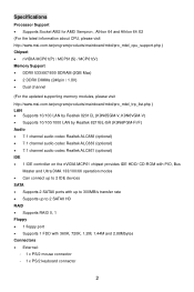
... is for electrical connection to a 2-pin chassis switch. If the mainboard has a System Hardware Monitor chipset on one cable, you must use a specially designed fan with +12V. MSI Reminds You... JFP1 is connected to the front panel switches and LEDs. If you install two hard ...Master, and Ultra DMA 66/100/133 function. The first hard drive should be connected to IDE1. MSI Reminds You... Each supports 2nd generation serial ATA data rates of 300 MB/s. MSI Reminds You... L GND 1 CINTRU 2 GND Fan Power Connectors: CPUFAN1/SYSFAN1 The 4-pin CPUFAN1 (processor...
... is for electrical connection to a 2-pin chassis switch. If the mainboard has a System Hardware Monitor chipset on one cable, you must use a specially designed fan with +12V. MSI Reminds You... JFP1 is connected to the front panel switches and LEDs. If you install two hard ...Master, and Ultra DMA 66/100/133 function. The first hard drive should be connected to IDE1. MSI Reminds You... Each supports 2nd generation serial ATA data rates of 300 MB/s. MSI Reminds You... L GND 1 CINTRU 2 GND Fan Power Connectors: CPUFAN1/SYSFAN1 The 4-pin CPUFAN1 (processor...
User Guide
Page 15
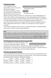
... meet your needs. Note: System default is to make sure that you to insert the expansion cards to enter the mainboard BIOS and select Advanced Chipset Features -> OnChip and PCIe VGA selection -> Both exist and Oncip VGA by frame buffer select. If you would like to use both onboard and expansion...
... meet your needs. Note: System default is to make sure that you to insert the expansion cards to enter the mainboard BIOS and select Advanced Chipset Features -> OnChip and PCIe VGA selection -> Both exist and Oncip VGA by frame buffer select. If you would like to use both onboard and expansion...
User Guide
Page 16
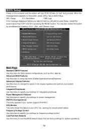
...Defaults Use this menu to specify your settings for integrated peripherals. Main Page Standard CMOS Features Use this menu to enter Setup. Advanced Chipset Features Use this menu to specify your settings for power management. Integrated Peripherals Use this menu to enter Setup, restart the system ... wish to setup the items of your system supports PnP/PCI. Advanced BIOS Features Use this menu to change the values in the chipset registers and optimize your system performance. Frequency/Voltage Control Use this menu for basic system configurations, such as time, date etc. When...
...Defaults Use this menu to specify your settings for integrated peripherals. Main Page Standard CMOS Features Use this menu to enter Setup. Advanced Chipset Features Use this menu to specify your settings for power management. Integrated Peripherals Use this menu to enter Setup, restart the system ... wish to setup the items of your system supports PnP/PCI. Advanced BIOS Features Use this menu to change the values in the chipset registers and optimize your system performance. Frequency/Voltage Control Use this menu for basic system configurations, such as time, date etc. When...
User Guide
Page 66
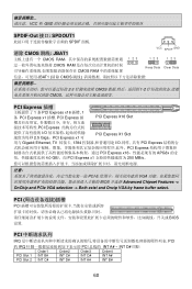
... PCI Express PCI Express x16 APG8x 的 2 4.0 GB/,而 PCI Express x1 250 MB/s.. 注意: PCI-E VGA BIOS 并选择 Advanced Chipset Features -> OnChip and PCIe VGA selection -> Both exist and Oncip VGA by frame buffer select.
... PCI Express PCI Express x16 APG8x 的 2 4.0 GB/,而 PCI Express x1 250 MB/s.. 注意: PCI-E VGA BIOS 并选择 Advanced Chipset Features -> OnChip and PCIe VGA selection -> Both exist and Oncip VGA by frame buffer select.
User Guide
Page 78
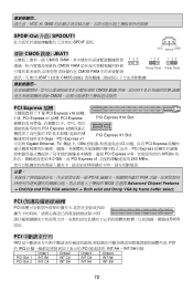
...; PCI Express PCI Express x16 APG8x 的 2 4.0 GB/,而 PCI Express x1 250 MB/s.. 注意: PCI-E VGA BIOS 並選擇 Advanced Chipset Features -> OnChip and PCIe VGA selection -> Both exist and Oncip VGA by frame buffer select. VCC 和 GND SPDIF-Out 介面: SPDOUT1 SPDIF 面...
...; PCI Express PCI Express x16 APG8x 的 2 4.0 GB/,而 PCI Express x1 250 MB/s.. 注意: PCI-E VGA BIOS 並選擇 Advanced Chipset Features -> OnChip and PCIe VGA selection -> Both exist and Oncip VGA by frame buffer select. VCC 和 GND SPDIF-Out 介面: SPDOUT1 SPDIF 面...
User Guide
Page 91
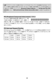
VGA VGA と拡張 VGA BIOS Advanced Chipset Features」の「OnChip and PCIe VGA selection Both exist and Oncip VGA by frame buffer select PCI (Peripheral Component Interconnect PCI BIOS PCI Interrupt Request Routing IRQ(interrupt request line I-R-Q PCI の IRQ PCI バス INT A# から INT D Order1 Order2 Order3 Order4 PCI Slot 1 INT B# INT C# INT D# INT A# PCI Slot 2 INT C# INT D# INT A# INT B# 85
VGA VGA と拡張 VGA BIOS Advanced Chipset Features」の「OnChip and PCIe VGA selection Both exist and Oncip VGA by frame buffer select PCI (Peripheral Component Interconnect PCI BIOS PCI Interrupt Request Routing IRQ(interrupt request line I-R-Q PCI の IRQ PCI バス INT A# から INT D Order1 Order2 Order3 Order4 PCI Slot 1 INT B# INT C# INT D# INT A# PCI Slot 2 INT C# INT D# INT A# INT B# 85