User Guide
Page 8
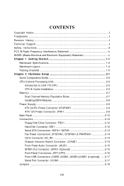
... 1-1 Mainboard Specifications 1-2 Mainboard Layout 1-4 Packing Checklist 1-5 Chapter 2 Hardware Setup 2-1 Quick Components Guide 2-2 CPU (Central Processing Unit 2-3 Introduction to LGA 775 CPU 2-3 CPU & Cooler Installation 2-4 Memory ...2-7 Dual Channel Memory Population Rules 2-7 Installing DDRII Modules 2-8 Power Supply ...2-9 ATX 24-Pin Power Connector: ATXPWR1 2-9 ATX 12V Power Connector: JPW 1 2-9 Back Panel ...2-10 Connectors ...2-12 Floppy Disk Drive Connector...
... 1-1 Mainboard Specifications 1-2 Mainboard Layout 1-4 Packing Checklist 1-5 Chapter 2 Hardware Setup 2-1 Quick Components Guide 2-2 CPU (Central Processing Unit 2-3 Introduction to LGA 775 CPU 2-3 CPU & Cooler Installation 2-4 Memory ...2-7 Dual Channel Memory Population Rules 2-7 Installing DDRII Modules 2-8 Power Supply ...2-9 ATX 24-Pin Power Connector: ATXPWR1 2-9 ATX 12V Power Connector: JPW 1 2-9 Back Panel ...2-10 Connectors ...2-12 Floppy Disk Drive Connector...
User Guide
Page 12
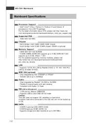
... PCI LAN by VIA VT6308P or VT6307 - p hp LAN - Supports USB to OS. A system hard drive connected to this IDE slot can not be booted up to 400Mbps Audio - For the latest information about CPU, please visit http://www.msi. t w / program /product s/ m ai nboard/m bd/ ...JMB20335 - Chip integrated by 8110SB/ 8110SC IEEE 1394 (optional) - Chip integrated by ICH8R (SATA1~6) - c om . MS-7241 Mainboard Mainboard Specifications Processor Support - Intel® CoreTM 2 Duo, Pentium 4, Pentium D and Celeron D processors in hard drive. c om . North Bridge: Intel® G965/ ...
... PCI LAN by VIA VT6308P or VT6307 - p hp LAN - Supports USB to OS. A system hard drive connected to this IDE slot can not be booted up to 400Mbps Audio - For the latest information about CPU, please visit http://www.msi. t w / program /product s/ m ai nboard/m bd/ ...JMB20335 - Chip integrated by 8110SB/ 8110SC IEEE 1394 (optional) - Chip integrated by ICH8R (SATA1~6) - c om . MS-7241 Mainboard Mainboard Specifications Processor Support - Intel® CoreTM 2 Duo, Pentium 4, Pentium D and Celeron D processors in hard drive. c om . North Bridge: Intel® G965/ ...

User Guide
Page 18
... Yellow triangle is the Pin 1 indicator 2-3 W hen you apply an even layer of LGA 775 CPU. For the latest information about CPU, please visit http://www.msi.com.tw/program/ products/mainboard/mbd/pro_mbd_cpu_support.php Important 1. Make sure that you are installing the...dissipation. 3. Introduction to ensure the safety of LGA 775 CPU. While replacing the CPU, always turn off the ATX power supply or unplug the power supply's power cord from overheating. 2. Hardware Setup CPU (Central Processing Unit) This mainboard supports Intel® CoreTM 2 Duo, Pentium 4, Pentium D, Celeron...
... Yellow triangle is the Pin 1 indicator 2-3 W hen you apply an even layer of LGA 775 CPU. For the latest information about CPU, please visit http://www.msi.com.tw/program/ products/mainboard/mbd/pro_mbd_cpu_support.php Important 1. Make sure that you are installing the...dissipation. 3. Introduction to ensure the safety of LGA 775 CPU. While replacing the CPU, always turn off the ATX power supply or unplug the power supply's power cord from overheating. 2. Hardware Setup CPU (Central Processing Unit) This mainboard supports Intel® CoreTM 2 Duo, Pentium 4, Pentium D, Celeron...

User Guide
Page 29
...-ROM audio. The system will be connected to GND. CINTRU 1 JCASE1 GND 2-14 W hen connecting the wire to the connectors, always take advantage of the CPU fan c on tr ol . CD_IN1 L GND R Chassis Intrusion Switch Connector: JCASE1 This connector connects to a 2-pin chassis switch. If the mainboard has a ...on-board, you must use a specially designed fan with +12V. MS-7241 Mainboard Fan Power Connectors: CPUFAN1, SYSFAN1 & PWRFAN1 The fan power connectors support system cooling fan with speed sensor to take note that the red wire is the positive and should be short.
...-ROM audio. The system will be connected to GND. CINTRU 1 JCASE1 GND 2-14 W hen connecting the wire to the connectors, always take advantage of the CPU fan c on tr ol . CD_IN1 L GND R Chassis Intrusion Switch Connector: JCASE1 This connector connects to a 2-pin chassis switch. If the mainboard has a ...on-board, you must use a specially designed fan with +12V. MS-7241 Mainboard Fan Power Connectors: CPUFAN1, SYSFAN1 & PWRFAN1 The fan power connectors support system cooling fan with speed sensor to take note that the red wire is the positive and should be short.

User Guide
Page 45
... Boot Device & Boot From Other Device The items allow you to select which version to select the MPS version supported by your operating system doesn't support HT Function, or unreliability and instability may occur. MPS Table Version This field allows you to load the disk ... of the following platform Components: * CPU: An Intel® Pentium® 4 Processor with HT Technology; * Chipset: An Intel® Chipset that supports HT Technology; * BIOS: A BIOS that supports HT Technology and has it enabled; * OS: An operating system that supports HT Technology. For more information on ...
... Boot Device & Boot From Other Device The items allow you to select which version to select the MPS version supported by your operating system doesn't support HT Function, or unreliability and instability may occur. MPS Table Version This field allows you to load the disk ... of the following platform Components: * CPU: An Intel® Pentium® 4 Processor with HT Technology; * Chipset: An Intel® Chipset that supports HT Technology; * BIOS: A BIOS that supports HT Technology and has it enabled; * OS: An operating system that supports HT Technology. For more information on ...

User Guide
Page 51
.... ACPI Standby State This item specifies the power saving modes for ACPI function. In this state, no system context is lost (CPU or chipset) and hardware main- If your BIOS supports S3 sleep mode. tains all system context. [S3/STR] The S3 sleep mode is a lower power state where the in... formation of this field. Set- The information stored in memory will be used to save energy. tings are available only when your operating system supports ACPI, such as W indows 2000/ XP, select [Yes]. ACPI Function This item is to enter the Standby mode in S1(POS) or S3(STR)...
.... ACPI Standby State This item specifies the power saving modes for ACPI function. In this state, no system context is lost (CPU or chipset) and hardware main- If your BIOS supports S3 sleep mode. tains all system context. [S3/STR] The S3 sleep mode is a lower power state where the in... formation of this field. Set- The information stored in memory will be used to save energy. tings are available only when your operating system supports ACPI, such as W indows 2000/ XP, select [Yes]. ACPI Function This item is to enter the Standby mode in S1(POS) or S3(STR)...

User Guide
Page 52
... off . Power Button Function This feature sets the function of time specified in this field, all devices except CPU will reboot after resuming from S3 when input signal of the card does not support the initialization feature, the display may work abnormally or not function after a power failure or interrupt occurs. Therefore...
... off . Power Button Function This feature sets the function of time specified in this field, all devices except CPU will reboot after resuming from S3 when input signal of the card does not support the initialization feature, the display may work abnormally or not function after a power failure or interrupt occurs. Therefore...


