User Guide
Page 10
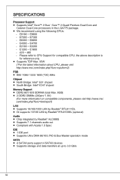
... data transfers at up to CPU Support for reference only. ■ Supports TDP Max. 95W (*For the latest information about CPU, please visit http://www.msi.com/index.php?func=cpuform2) FSB ■ 800/ 1066/ 1333/ 1600 (*OC) MHz Chipset ■ North Bridge: Intel® G31 chipset ■... South Bridge: Intel® ICH7 chipset Memory Support ■ DDR2 667/ 800 SDRAM (total Max. 8GB) ■ 2 DDR2 DIMMs (240pin/ 1.8V) (For more information on compatible components, please visit http://...
... data transfers at up to CPU Support for reference only. ■ Supports TDP Max. 95W (*For the latest information about CPU, please visit http://www.msi.com/index.php?func=cpuform2) FSB ■ 800/ 1066/ 1333/ 1600 (*OC) MHz Chipset ■ North Bridge: Intel® G31 chipset ■... South Bridge: Intel® ICH7 chipset Memory Support ■ DDR2 667/ 800 SDRAM (total Max. 8GB) ■ 2 DDR2 DIMMs (240pin/ 1.8V) (For more information on compatible components, please visit http://...
User Guide
Page 12
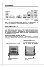
... installation, be output from front panel if you purchase the mainboard with 3 audio jacks HARDWARE SETUP This chapter tells you how to install the CPU, memory modules, and expansion cards, as well as the mouse, keyboard, etc. CPU & Cooler Installation Procedures for better heat dispersion. Remember to prevent overheating. If you...
... installation, be output from front panel if you purchase the mainboard with 3 audio jacks HARDWARE SETUP This chapter tells you how to install the CPU, memory modules, and expansion cards, as well as the mouse, keyboard, etc. CPU & Cooler Installation Procedures for better heat dispersion. Remember to prevent overheating. If you...
User Guide
Page 14
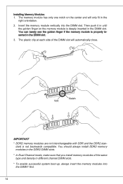
...DIMM slot. Notch Volt Important * DDR2 memory modules are not interchangeable with DDR and the DDR2 stan- You can barely see the golden finger if the memory module is not backwards compatible. The memory module has only one notch on the memory module is deeply inserted in different channel...slots. * To enable successful system boot-up, always insert the memory modules into the DIMM slot. Then push it in the right orientation. 2. Insert the memory module vertically into the DIMM1 first. 14 You should always install DDR2 memory modules in the DDR2 DIMM slots. * In Dual-Channel mode...
...DIMM slot. Notch Volt Important * DDR2 memory modules are not interchangeable with DDR and the DDR2 stan- You can barely see the golden finger if the memory module is not backwards compatible. The memory module has only one notch on the memory module is deeply inserted in different channel...slots. * To enable successful system boot-up, always insert the memory modules into the DIMM slot. Then push it in the right orientation. 2. Insert the memory module vertically into the DIMM1 first. 14 You should always install DDR2 memory modules in the DDR2 DIMM slots. * In Dual-Channel mode...
User Guide
Page 20
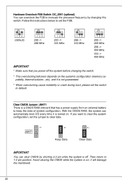
... the processor frequency by shorting 2-3 pin while the system is off the system before changing the switch. * This overclocking behavior depends on the system's configuration (memory capability, thermal solution...etc), and it will damage the mainboard. 20 Follow the instructions below to set the switch to 1-2 pin position. it is turned...
... the processor frequency by shorting 2-3 pin while the system is off the system before changing the switch. * This overclocking behavior depends on the system's configuration (memory capability, thermal solution...etc), and it will damage the mainboard. 20 Follow the instructions below to set the switch to 1-2 pin position. it is turned...
User Guide
Page 24
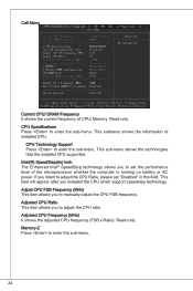
...ratio. Read-only. Read-only. This field will appear after you to adjust the CPU Ratio, please set the performance level of CPU/ Memory. Adjusted CPU Ratio This item allows you installed the CPU which support speedstep technology. Intel(R) SpeedStep(tm) tech The Enhanced Intel® ...SpeedStep technology allows you to enter the sub-menu. Memory-Z Press to enter the sub-menu. CPU Technology Support Press to set "Disabled" in this field. This submenu shows the information of installed...
...ratio. Read-only. Read-only. This field will appear after you to adjust the CPU Ratio, please set the performance level of CPU/ Memory. Adjusted CPU Ratio This item allows you installed the CPU which support speedstep technology. Intel(R) SpeedStep(tm) tech The Enhanced Intel® ...SpeedStep technology allows you to enter the sub-menu. Memory-Z Press to enter the sub-menu. CPU Technology Support Press to set "Disabled" in this field. This submenu shows the information of installed...
User Guide
Page 25
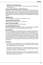
... may just cause your overclocked processor to minimize the electromagnetic interference (EMI). Adjusted DRAM Frequency (MHz) It shows the adjusted memory frequency. Auto Disable DRAM/PCI Frequency When set to Enabled for optimal system stability and performance. Important * If you do ...empty DIMM and PCI slots to lock up . Spread Spectrum When the motherboard's clock generator pulses, the extreme values (spikes) of installed memory. Setting to [By SPD] enables DRAM CAS# Latency automatically to memory. But if you are overclocking because even a slight jitter can introduce ...
... may just cause your overclocked processor to minimize the electromagnetic interference (EMI). Adjusted DRAM Frequency (MHz) It shows the adjusted memory frequency. Auto Disable DRAM/PCI Frequency When set to Enabled for optimal system stability and performance. Important * If you do ...empty DIMM and PCI slots to lock up . Spread Spectrum When the motherboard's clock generator pulses, the extreme values (spikes) of installed memory. Setting to [By SPD] enables DRAM CAS# Latency automatically to memory. But if you are overclocking because even a slight jitter can introduce ...
User Guide
Page 115
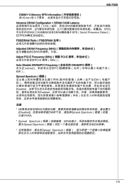
MS-7529 DIMM1~2 Memory SPD Information Enter Advance DRAM Configuration > DRAM CAS# Latency CAS DRAM 2T 2.5T By SPD DRAM CAS#由BIOS在DRAM模组基于...
MS-7529 DIMM1~2 Memory SPD Information Enter Advance DRAM Configuration > DRAM CAS# Latency CAS DRAM 2T 2.5T By SPD DRAM CAS#由BIOS在DRAM模组基于...
User Guide
Page 133
MS-7529 DIMM1~2 Memory SPD Information(DIMM1~2 記憶體 SPD Enter Advance DRAM Configuration > DRAM CAS# Latency (進階 DRAM 設定 > DRAM CAS CAS SDRAM 2T 2.5T By SPD BIOS 依 DRAM SPD EEPROM DRAM FSB/ DRAM Ratio (FSB FSB Adjusted DRAM Frequency (MHz Adjust PCI-E Frequency (MHz) (調整 PCI-E PCI-E 頻率。 Auto Disable DRAM/PCI Frequency PCI Enabled EMI)。 Spread Spectrum EMI EMI Disabled EMI Enabled EMI Disabled EMI 133
MS-7529 DIMM1~2 Memory SPD Information(DIMM1~2 記憶體 SPD Enter Advance DRAM Configuration > DRAM CAS# Latency (進階 DRAM 設定 > DRAM CAS CAS SDRAM 2T 2.5T By SPD BIOS 依 DRAM SPD EEPROM DRAM FSB/ DRAM Ratio (FSB FSB Adjusted DRAM Frequency (MHz Adjust PCI-E Frequency (MHz) (調整 PCI-E PCI-E 頻率。 Auto Disable DRAM/PCI Frequency PCI Enabled EMI)。 Spread Spectrum EMI EMI Disabled EMI Enabled EMI Disabled EMI 133
User Guide
Page 151
MS-7529 DIMM1~2 Memory SPD Information (メモリSPD情報) DRAM CAS# Latency DRAMがCAS CAS 2.5T 2T By SPD DRAM CAS# Latency DRAM SPD EEPROM FSB/DRAM Ratio (FSB/DRAM倍率) FSB Adjusted DRAM Frequency (MHz DRAM Adjust PCI-E Frequency (MHz) (PCI-E PCI-E Auto Disable DRAM/PCI Frequency DRAM/PCI Enabled Spread Spectrum EMI Disabled Disabled めに[Disabled Enabled * Spread Spectrum Disabled 151
MS-7529 DIMM1~2 Memory SPD Information (メモリSPD情報) DRAM CAS# Latency DRAMがCAS CAS 2.5T 2T By SPD DRAM CAS# Latency DRAM SPD EEPROM FSB/DRAM Ratio (FSB/DRAM倍率) FSB Adjusted DRAM Frequency (MHz DRAM Adjust PCI-E Frequency (MHz) (PCI-E PCI-E Auto Disable DRAM/PCI Frequency DRAM/PCI Enabled Spread Spectrum EMI Disabled Disabled めに[Disabled Enabled * Spread Spectrum Disabled 151


