
RSL12VDC Sell Sheet Manual
Page 2
...the interrupt loop. MyQ Technology communication can be added to meet UL 325 standards. LiftMaster gate operators comply with a MyQ Enabled gate operator. Eight different settings, including .... 16.64 16.76 QUICK CLOSE Closes the gate immediately after using manual disconnect. FEATURES FIRE DEPARTMENT COMPLIANT Selectable settings allow gate to auto open and... OPTIONAL EXPANSION BOARD) Secures your property. Does not include added accessory power draw. RSL12VDC RESIDENTIAL/LIGHT COMMERCIAL DC SLIDE GATE OPERATOR LED DIAGNOSTIC DISPLAY Easy-to 140°F ...
...the interrupt loop. MyQ Technology communication can be added to meet UL 325 standards. LiftMaster gate operators comply with a MyQ Enabled gate operator. Eight different settings, including .... 16.64 16.76 QUICK CLOSE Closes the gate immediately after using manual disconnect. FEATURES FIRE DEPARTMENT COMPLIANT Selectable settings allow gate to auto open and... OPTIONAL EXPANSION BOARD) Secures your property. Does not include added accessory power draw. RSL12VDC RESIDENTIAL/LIGHT COMMERCIAL DC SLIDE GATE OPERATOR LED DIAGNOSTIC DISPLAY Easy-to 140°F ...

Solar Chart Manual
Page 1
... 106 35 #NUM! Control Board Feature Main board with no radios learned (mA) One or more LiftMaster® transmitters learned (mA) MyQ® device or wireless dual gate learned (mA) Expansion board...LA500DC, LA400DC) configurations. LA412DC Current consumption by control board feature 12v (RSW12VDC, RSL12VDC) configurations. RSL12VDC / RSW12VDC Current consumption by control board feature 12v (LA412DC) configurations. RSW 12VDC...of wired dual gate installation. For full details please reference the manual. Add up current draw by feature and accessory to determine total...
... 106 35 #NUM! Control Board Feature Main board with no radios learned (mA) One or more LiftMaster® transmitters learned (mA) MyQ® device or wireless dual gate learned (mA) Expansion board...LA500DC, LA400DC) configurations. LA412DC Current consumption by control board feature 12v (RSW12VDC, RSL12VDC) configurations. RSL12VDC / RSW12VDC Current consumption by control board feature 12v (LA412DC) configurations. RSW 12VDC...of wired dual gate installation. For full details please reference the manual. Add up current draw by feature and accessory to determine total...

Solar Chart Manual
Page 2
... CSL24VDC (2) 33-AH batteries recommended in lieu of standard 7-AH batteries RSW12VDC, RSL12VDC (1) 33-AH batteries recommended in Accessory Line LiftMaster Solar Gate Operators are expected over several days, the manual disconnect may be engaged and the gate left open area clear of the solar ...determined by whether the application is due to conserve additional power draw (11mA) CSW 24VDC Gate solar cycles per Day Reference Guide LiftMaster Solar Gate Operators feature a best in class power management system that experience cold temperatures below 32°F (0°C) for more ...
... CSL24VDC (2) 33-AH batteries recommended in lieu of standard 7-AH batteries RSW12VDC, RSL12VDC (1) 33-AH batteries recommended in Accessory Line LiftMaster Solar Gate Operators are expected over several days, the manual disconnect may be engaged and the gate left open area clear of the solar ...determined by whether the application is due to conserve additional power draw (11mA) CSW 24VDC Gate solar cycles per Day Reference Guide LiftMaster Solar Gate Operators feature a best in class power management system that experience cold temperatures below 32°F (0°C) for more ...
RSL12VDC Installation Manual
Page 2
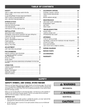
...DUAL GATES ONLY 15 INSTALL THE COVER 17 ADJUSTMENT 18 LIMIT AND FORCE ADJUSTMENT 18 PROGRAMMING 20 REMOTE CONTROLS (NOT PROVIDED 20 LIFTMASTER INTERNET GATEWAY (NOT PROVIDED 21 ERASE ALL CODES 21 ERASE LIMITS 21 TO REMOVE AND ERASE MONITORED ENTRAPMENT PROTECTION DEVICES 21 ...OPERATION 22 CONTROL BOARD OVERVIEW 22 RESET SWITCH 23 MANUAL DISCONNECT 23 OPERATOR ALARM 23 REMOTE CONTROL 23 ACCESSORY WIRING 24 EXTERNAL CONTROL DEVICES 24 VEHICLE DETECTION DEVICES 24 LOCKS 25 ...
...DUAL GATES ONLY 15 INSTALL THE COVER 17 ADJUSTMENT 18 LIMIT AND FORCE ADJUSTMENT 18 PROGRAMMING 20 REMOTE CONTROLS (NOT PROVIDED 20 LIFTMASTER INTERNET GATEWAY (NOT PROVIDED 21 ERASE ALL CODES 21 ERASE LIMITS 21 TO REMOVE AND ERASE MONITORED ENTRAPMENT PROTECTION DEVICES 21 ...OPERATION 22 CONTROL BOARD OVERVIEW 22 RESET SWITCH 23 MANUAL DISCONNECT 23 OPERATOR ALARM 23 REMOTE CONTROL 23 ACCESSORY WIRING 24 EXTERNAL CONTROL DEVICES 24 VEHICLE DETECTION DEVICES 24 LOCKS 25 ...

RSL12VDC Installation Manual
Page 3
... or loading dock area or other restricted access locations not servicing the general public, in which unauthorized access is for vehicles ONLY. Read the owner's manual. SAFETY USAGE CLASS CLASS I A vehicular gate operator (or system) intended for use in garages or parking areas associated with Type A. Use of INJURY or DEATH...
... or loading dock area or other restricted access locations not servicing the general public, in which unauthorized access is for vehicles ONLY. Read the owner's manual. SAFETY USAGE CLASS CLASS I A vehicular gate operator (or system) intended for use in garages or parking areas associated with Type A. Use of INJURY or DEATH...

RSL12VDC Installation Manual
Page 4
... outside of application. The gate must reduce public exposure to prevent a 2-1/4 inches (6 cm) diameter sphere from reaching over, under the intended end-use . Reference owner's manual regarding placement of a vertical barrier (arm). 3 A wireless device such as when a vehicle trips the sensor while the gate is greater than 6 inches (152 mm) above...
... outside of application. The gate must reduce public exposure to prevent a 2-1/4 inches (6 cm) diameter sphere from reaching over, under the intended end-use . Reference owner's manual regarding placement of a vertical barrier (arm). 3 A wireless device such as when a vehicle trips the sensor while the gate is greater than 6 inches (152 mm) above...

RSL12VDC Installation Manual
Page 5
... 8 feet (2.44 m) above grade and for barbed wire shall not be less than 6 feet (1.83 m) above grade. 1.5 An existing gate latch shall be disabled when a manually operated gate is retrofitted with a powered gate operator. 1.6 A gate latch shall not be installed on an automatically operated gate. 1.7 Protrusions shall not be permitted on...
... 8 feet (2.44 m) above grade and for barbed wire shall not be less than 6 feet (1.83 m) above grade. 1.5 An existing gate latch shall be disabled when a manually operated gate is retrofitted with a powered gate operator. 1.6 A gate latch shall not be installed on an automatically operated gate. 1.7 Protrusions shall not be permitted on...

RSL12VDC Installation Manual
Page 9
NOTE: One or more non-contact sensors shall be located where the risk of the manual for more information). SINGLE GATE Warning Sign Safety Catch Roller Edge Sensor Edge Sensor Photoelectric Sensors Operator DUAL GATE Earth Ground Rod Check national and ...
NOTE: One or more non-contact sensors shall be located where the risk of the manual for more information). SINGLE GATE Warning Sign Safety Catch Roller Edge Sensor Edge Sensor Photoelectric Sensors Operator DUAL GATE Earth Ground Rod Check national and ...

RSL12VDC Installation Manual
Page 11
Pour a concrete pad (reinforced concrete is recommended). DO NOT run the operator until instructed. 1. Install the electrical conduit. 2. Manually close the gate and line up the front bracket so the chain will be too tight or have no more than the frost line. 3. Attach ... ATTACHMENT Check the national and local building codes before installation. 1. NOTE: The chain should be level with the idler pulley and parallel to the ground. Manually open the gate and line up the rear bracket so the chain will be 6 inches above the ground and deeper than 1 inch of sag for...
Pour a concrete pad (reinforced concrete is recommended). DO NOT run the operator until instructed. 1. Install the electrical conduit. 2. Manually close the gate and line up the front bracket so the chain will be too tight or have no more than the frost line. 3. Attach ... ATTACHMENT Check the national and local building codes before installation. 1. NOTE: The chain should be level with the idler pulley and parallel to the ground. Manually open the gate and line up the rear bracket so the chain will be 6 inches above the ground and deeper than 1 inch of sag for...
RSL12VDC Installation Manual
Page 13
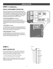
... sensor entrapment protection for proper depth 12 INSTALLATION STEP 4 continued... This input will be wired to the wiring diagram or the specific entrapment protection device manual for monitored devices, which include pulsed photoelectric sensors, resistive edge sensors, and pulsed edge sensors. The ground wire must be disregarded during gate opening . To...
... sensor entrapment protection for proper depth 12 INSTALLATION STEP 4 continued... This input will be wired to the wiring diagram or the specific entrapment protection device manual for monitored devices, which include pulsed photoelectric sensors, resistive edge sensors, and pulsed edge sensors. The ground wire must be disregarded during gate opening . To...
RSL12VDC Installation Manual
Page 23
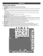
... or battery voltage increases. • Option select switch set to automatically close the gate after the operator type, example "1.2". 12 BACKDRIVE Switch: Set to MANUAL will allow the gate to be set to CLOSE forces gate to latch at CLOSE limit if at CLOSE limit or on next CLOSE command...type will either open controls, loops, close edges, and close the gate when the operator is reset by a "12" which indicates the operator type as RSL12VDC. See Adjust Limits section. 2 SET CLOSE Button: The SET CLOSE button sets the CLOSE limit. The TTC is in the Troubleshooting section. 11 Error Code...
... or battery voltage increases. • Option select switch set to automatically close the gate after the operator type, example "1.2". 12 BACKDRIVE Switch: Set to MANUAL will allow the gate to be set to CLOSE forces gate to latch at CLOSE limit if at CLOSE limit or on next CLOSE command...type will either open controls, loops, close edges, and close the gate when the operator is reset by a "12" which indicates the operator type as RSL12VDC. See Adjust Limits section. 2 SET CLOSE Button: The SET CLOSE button sets the CLOSE limit. The TTC is in the Troubleshooting section. 11 Error Code...

RSL12VDC Installation Manual
Page 24
...reset switch to shut off the gate rail. The operator alarm will beep 3 times with a command if the battery is in the closed manually. C. Remove any obstructions. E REMOTE CONTROL SINGLE BUTTON CONTROL (SBC) FUNCTIONALITY Once the remote control has been programmed the operator will operate as... the solenoid lock for two minutes and disable the maglock for two minutes. B. C E. Toggle the reset switch to NORMAL OPERATION. MANUAL DISCONNECT Press the reset switch to RESET/DISCONNECT to allow the gate to be opened and closed position, activation of the remote control button...
...reset switch to shut off the gate rail. The operator alarm will beep 3 times with a command if the battery is in the closed manually. C. Remove any obstructions. E REMOTE CONTROL SINGLE BUTTON CONTROL (SBC) FUNCTIONALITY Once the remote control has been programmed the operator will operate as... the solenoid lock for two minutes and disable the maglock for two minutes. B. C E. Toggle the reset switch to NORMAL OPERATION. MANUAL DISCONNECT Press the reset switch to RESET/DISCONNECT to allow the gate to be opened and closed position, activation of the remote control button...

RSL12VDC Installation Manual
Page 27
... • ALWAYS wear protective gloves and eye protection when changing the battery or working around the battery compartment. Pedestrians MUST use ONLY LiftMaster part 29-NP712 for proper operation Inspect all power (AC, solar, battery) to the operator or in extremely cold temperatures. The ... make repairs to gate hardware. • ALL maintenance MUST be performed by a LiftMaster professional. • Activate gate ONLY when it can increase the risk of INJURY or DEATH. • Use the manual disconnect release ONLY when the gate is within ten percent of the operator's rating....
... • ALWAYS wear protective gloves and eye protection when changing the battery or working around the battery compartment. Pedestrians MUST use ONLY LiftMaster part 29-NP712 for proper operation Inspect all power (AC, solar, battery) to the operator or in extremely cold temperatures. The ... make repairs to gate hardware. • ALL maintenance MUST be performed by a LiftMaster professional. • Activate gate ONLY when it can increase the risk of INJURY or DEATH. • Use the manual disconnect release ONLY when the gate is within ten percent of the operator's rating....
RSL12VDC Installation Manual
Page 32
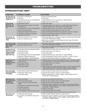
a) Use manual disconnect, manually move limits. Repair gate as needed . Re-learn wireless control/transmitter to -Close (TTC) setting g) Check all Entrapment Protection Device inputs for an active sensor a) ... or vehicle probe active f) Check all vehicle detector inputs for a "stuck on the stop circuit. b) Check Stop button is too difficult to move a) Use manual disconnect, manually move easily and freely through its entire range, limit to limit. Check operator's antenna and antenna wire. Charge batteries by AC or solar power or...
a) Use manual disconnect, manually move limits. Repair gate as needed . Re-learn wireless control/transmitter to -Close (TTC) setting g) Check all Entrapment Protection Device inputs for an active sensor a) ... or vehicle probe active f) Check all vehicle detector inputs for a "stuck on the stop circuit. b) Check Stop button is too difficult to move a) Use manual disconnect, manually move easily and freely through its entire range, limit to limit. Check operator's antenna and antenna wire. Charge batteries by AC or solar power or...

RSL12VDC Installation Manual
Page 36
... ground. Align the top bracket so the chain will be installed near the front roller of the gate or near the back of chain length. Manually close the gate and align the bottom bracket so the chain will require two extra idler pulleys. Make sure all 4 exposed pinch points are guarded...
... ground. Align the top bracket so the chain will be installed near the front roller of the gate or near the back of chain length. Manually close the gate and align the bottom bracket so the chain will require two extra idler pulleys. Make sure all 4 exposed pinch points are guarded...

RSL12VDC Installation Manual
Page 43
... CLOSE 1 EYE ONLY 2 EYE/ EDGE 3 EYE/ EDGE COM SBC OPN CLS STP COM EYE EDGE OR EYE EDGE OR EYE N.C. Jumper Wire WARNING: See Installation Manual regarding maintenance and required safety testing prior to the chassis ground of same type and rating. For continued protection against fire and electrocution: • DISCONNECT...
... CLOSE 1 EYE ONLY 2 EYE/ EDGE 3 EYE/ EDGE COM SBC OPN CLS STP COM EYE EDGE OR EYE EDGE OR EYE N.C. Jumper Wire WARNING: See Installation Manual regarding maintenance and required safety testing prior to the chassis ground of same type and rating. For continued protection against fire and electrocution: • DISCONNECT...


