
Solar Gate Access System Daily Cycle Chart Manual
Page 1
... 31 11 10W (12V) panels in series. 100 13 0 122 71 48 40W SOLAR PANEL 50 98 50 28 NOTE: 40W would be two 20W (12V) panels in ThPeoLwAe4r1i2s SporolavridGeadtetoActcheessgaStyestoepmeruatitloizrevsiathebainttneorvieasti.ve EvercClhimaragtee®sPwohweerreMteamnapgeermateunrteSsyrsetaecmhtobedleoliwve-r4p°oFw. Sorelagriopannse. LA500 not supported/available in an open area clear LAipnon4wo1ve2ar twiSvheoePnloanwereeGrdMeadatnmeaogAsetcmfocerneot spSeysrsatSteinmygstaotegdaemtleivewDrhaileily Cycle Chart...
... 31 11 10W (12V) panels in series. 100 13 0 122 71 48 40W SOLAR PANEL 50 98 50 28 NOTE: 40W would be two 20W (12V) panels in ThPeoLwAe4r1i2s SporolavridGeadtetoActcheessgaStyestoepmeruatitloizrevsiathebainttneorvieasti.ve EvercClhimaragtee®sPwohweerreMteamnapgeermateunrteSsyrsetaecmhtobedleoliwve-r4p°oFw. Sorelagriopannse. LA500 not supported/available in an open area clear LAipnon4wo1ve2ar twiSvheoePnloanwereeGrdMeadatnmeaogAsetcmfocerneot spSeysrsatSteinmygstaotegdaemtleivewDrhaileily Cycle Chart...
"Manufacturer's Certification for Credit" Manual
Page 1
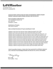
...Woi g Vice President - LiftMaster LA412 Solar Gate Operator System (Single Gate Model LA412-1PKG) LiftMaster LA412 Solar Gate Operator System (Duel Gate Model LA412-2PKG) LiftMaster RSL12V Residential DC Slide Gate Operator System (Single Gate Model RSL-12V) LiftMaster RSL12V Residential DC Slide Gate...System (Single Gate Model CSW24V) LiftMaster CSW24V Commercial DC Swing Gate Operator System (Duel Gate Model CSW24V) LiftMaster LA500 DC Swing Gate Operator System (Single Gate Model LA500-1PKG) LiftMaster LA500 DC Swing Gate Operator System (Duel Gate Model LA500-2PKG) Under the penalties of ...
...Woi g Vice President - LiftMaster LA412 Solar Gate Operator System (Single Gate Model LA412-1PKG) LiftMaster LA412 Solar Gate Operator System (Duel Gate Model LA412-2PKG) LiftMaster RSL12V Residential DC Slide Gate Operator System (Single Gate Model RSL-12V) LiftMaster RSL12V Residential DC Slide Gate...System (Single Gate Model CSW24V) LiftMaster CSW24V Commercial DC Swing Gate Operator System (Duel Gate Model CSW24V) LiftMaster LA500 DC Swing Gate Operator System (Single Gate Model LA500-1PKG) LiftMaster LA500 DC Swing Gate Operator System (Duel Gate Model LA500-2PKG) Under the penalties of ...

LA500 Manual
Page 8
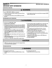
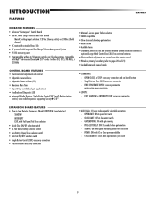
... install an edge sensor BEFORE proceeding with the control station installation. • ALL power wiring should be performed until disconnecting the electrical power (AC or solar and battery) and locking-out the power via the operator power switch. Gate MUST reverse on EACH side of INJURY at the leading and trailing...
... install an edge sensor BEFORE proceeding with the control station installation. • ALL power wiring should be performed until disconnecting the electrical power (AC or solar and battery) and locking-out the power via the operator power switch. Gate MUST reverse on EACH side of INJURY at the leading and trailing...
LA500 Manual
Page 9
...fire: • Replace ONLY with national and local electrical codes. Operator MUST be performed until disconnecting the electrical power (AC or solar and battery) and locking-out the power via the operator power switch. Have a qualified service person make repairs to protect anyone who.... • Disconnect power at that time the unit may be installed to gate hardware. • ALL maintenance MUST be performed by a LiftMaster professional. • Activate gate ONLY when it can increase the risk of same type and rating. 7 For continued protection against fire and electrocution...
...fire: • Replace ONLY with national and local electrical codes. Operator MUST be performed until disconnecting the electrical power (AC or solar and battery) and locking-out the power via the operator power switch. Have a qualified service person make repairs to protect anyone who.... • Disconnect power at that time the unit may be installed to gate hardware. • ALL maintenance MUST be performed by a LiftMaster professional. • Activate gate ONLY when it can increase the risk of same type and rating. 7 For continued protection against fire and electrocution...
LA500 Manual
Page 10
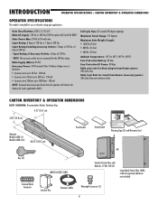
...176;C to 60°C (-40°F to 1000 feet - 100 mA NOTE: Increased accessory power drawn from the operator will shorten the battery life (solar applications ONLY). Input Rating: 8 Amps at 120 Vac or 1 Amp at 240 Vac Input Rating Excluding Accessory Outlets: 2 Amps at 120 Vac or 1....35" (102.5 cm) Post Bracket Gate Bracket Warning Signs (2) and Warranty Card OR Key (2) Terminal Block Connector MODEL LA500-S ONLY Standard Control Box with Toroid Kit ONLY) Solar Power Max: 24 Vdc at 120 Vac *NOTE: The accessory outlets are not connected for use in vehicular swing gate applications...
...176;C to 60°C (-40°F to 1000 feet - 100 mA NOTE: Increased accessory power drawn from the operator will shorten the battery life (solar applications ONLY). Input Rating: 8 Amps at 120 Vac or 1 Amp at 240 Vac Input Rating Excluding Accessory Outlets: 2 Amps at 120 Vac or 1....35" (102.5 cm) Post Bracket Gate Bracket Warning Signs (2) and Warranty Card OR Key (2) Terminal Block Connector MODEL LA500-S ONLY Standard Control Box with Toroid Kit ONLY) Solar Power Max: 24 Vdc at 120 Vac *NOTE: The accessory outlets are not connected for use in vehicular swing gate applications...
LA500 Manual
Page 11
INTEGRATED RADIO RECEIVER: • LOOPS: - GATE MOVING: ON with AC or Solar power available - TAMPER: ON when gate manually pulled from the remote control • Wireless primary/secondary (refer to pages 20 and 21) • Lockable manual ...
INTEGRATED RADIO RECEIVER: • LOOPS: - GATE MOVING: ON with AC or Solar power available - TAMPER: ON when gate manually pulled from the remote control • Wireless primary/secondary (refer to pages 20 and 21) • Lockable manual ...
LA500 Manual
Page 20
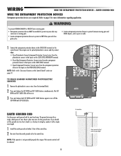
These inputs are required. J15 + BATT - + DC POWER BR GRN WT YE BLU RED BR GRN WT YE BLU RED SOLAR / CHARGER + LOCK LA S 2 U P Y 4V L S GROUND ID RESET ALARM ACCESSORY POWER + ON- + SW-. BOAR EARTH GROUND ROD Use the proper earth ground rod for the ground ...
These inputs are required. J15 + BATT - + DC POWER BR GRN WT YE BLU RED BR GRN WT YE BLU RED SOLAR / CHARGER + LOCK LA S 2 U P Y 4V L S GROUND ID RESET ALARM ACCESSORY POWER + ON- + SW-. BOAR EARTH GROUND ROD Use the proper earth ground rod for the ground ...
LA500 Manual
Page 24
... wire to NEUTRAL using a wire nut. 6 Connect the black wire to HOT using an external receiver use shielded wire for either 120 Vac (standard) or a solar panel (not provided). Main power supply and control wiring MUST be run in separate conduits. gate/ 19 ft. 500 lb. Refer to the Accessory page...
... wire to NEUTRAL using a wire nut. 6 Connect the black wire to HOT using an external receiver use shielded wire for either 120 Vac (standard) or a solar panel (not provided). Main power supply and control wiring MUST be run in separate conduits. gate/ 19 ft. 500 lb. Refer to the Accessory page...
LA500 Manual
Page 25
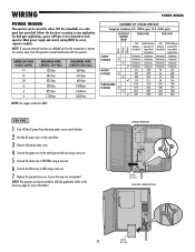
...area clear of two 10W solar panels in the solar/charge plug. CLASS 2 SUPPLY 24 VOLTS EXP. WIRING POWER WIRING CONTINUED... SOLAR PANEL(S) NOT PROVIDED. This is due to ensure proper operation. Solar panels should be cleaned on the control board. We recommend LiftMaster low power draw accessories to... minimize power draw, refer to the J15 plug labeled BATT(-)(+) DC(-)(+) on a regular basis for best performance to cold weather and a reduced number of hours of the other solar panel. 3 Connect the remaining red ...
...area clear of two 10W solar panels in the solar/charge plug. CLASS 2 SUPPLY 24 VOLTS EXP. WIRING POWER WIRING CONTINUED... SOLAR PANEL(S) NOT PROVIDED. This is due to ensure proper operation. Solar panels should be cleaned on the control board. We recommend LiftMaster low power draw accessories to... minimize power draw, refer to the J15 plug labeled BATT(-)(+) DC(-)(+) on a regular basis for best performance to cold weather and a reduced number of hours of the other solar panel. 3 Connect the remaining red ...
LA500 Manual
Page 26
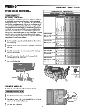
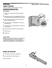
... Connect the black wire from the J15 plug labeled BATT (-) to the J15 plug labeled BATT(-)(+) DC(-)(+) on the control board by the transformer or solar panel. This engages the motor. 2 Turn the key clockwise 180°. A battery tray (model K10-36183) and battery harness (model K94-36596)... the battery. 6 Plug the J15 plug into the control board. WIRING CONNECT BATTERIES The batteries are required for a Large Metal Control Box (XLM) solar application ONLY. LARGE METAL CONTROL BOX (XLM) 7AH BATTERIES 1 Turn OFF AC power to the operator at the circuit breaker and unplug the transformer....
... Connect the black wire from the J15 plug labeled BATT (-) to the J15 plug labeled BATT(-)(+) DC(-)(+) on the control board by the transformer or solar panel. This engages the motor. 2 Turn the key clockwise 180°. A battery tray (model K10-36183) and battery harness (model K94-36596)... the battery. 6 Plug the J15 plug into the control board. WIRING CONNECT BATTERIES The batteries are required for a Large Metal Control Box (XLM) solar application ONLY. LARGE METAL CONTROL BOX (XLM) 7AH BATTERIES 1 Turn OFF AC power to the operator at the circuit breaker and unplug the transformer....
LA500 Manual
Page 31
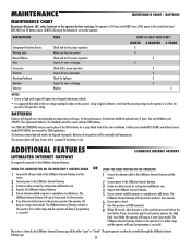
...for wear or damage Check all for proper operation Inspect all power (AC, solar, battery) to add devices. ADDITIONAL FEATURES LIFTMASTER INTERNET GATEWAY LIFTMASTER INTERNET GATEWAY To program the operator to the LiftMaster Internet Gateway: USING THE LEARN BUTTON ON THE OPERATOR'S CONTROL BOARD OR USING... "closed . Use an internet enabled computer or smartphone to be used in learn mode for a Large Metal Control Box solar installation. The LiftMaster Internet Gateway will pair to the operator it is within range and the operator will beep if programming is within range and...
...for wear or damage Check all for proper operation Inspect all power (AC, solar, battery) to add devices. ADDITIONAL FEATURES LIFTMASTER INTERNET GATEWAY LIFTMASTER INTERNET GATEWAY To program the operator to the LiftMaster Internet Gateway: USING THE LEARN BUTTON ON THE OPERATOR'S CONTROL BOARD OR USING... "closed . Use an internet enabled computer or smartphone to be used in learn mode for a Large Metal Control Box solar installation. The LiftMaster Internet Gateway will pair to the operator it is within range and the operator will beep if programming is within range and...
LA500 Manual
Page 32
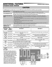
... expansion board connected. Switches Off to the desired setting. Always ON EXP. BOARD BR GRN WT YE BLU RED BR GRN WT YE BLU RED SOLAR / CHARGER + GROUND ID RESET ALARM 30 Rotate the TIMER-TO-CLOSE dial to save L battery power if expansion board disconnected. OPEN CLOSE STOP SET OPEN...
... expansion board connected. Switches Off to the desired setting. Always ON EXP. BOARD BR GRN WT YE BLU RED BR GRN WT YE BLU RED SOLAR / CHARGER + GROUND ID RESET ALARM 30 Rotate the TIMER-TO-CLOSE dial to save L battery power if expansion board disconnected. OPEN CLOSE STOP SET OPEN...
LA500 Manual
Page 34
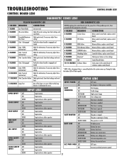
... a stopped gate to close (ignores the Timer-to conserve battery power. light). warning light or sounder). Power ON ON OFF Energizes when AC power or solar power is 163,000.). See below. Cycle count is present. Cycle count cannot be reset or changed. BATT: With loss of AC power will remain...
... a stopped gate to close (ignores the Timer-to conserve battery power. light). warning light or sounder). Power ON ON OFF Energizes when AC power or solar power is 163,000.). See below. Cycle count is present. Cycle count cannot be reset or changed. BATT: With loss of AC power will remain...
LA500 Manual
Page 38
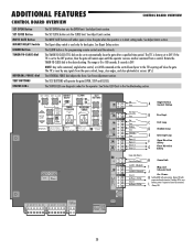
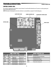
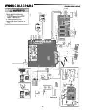
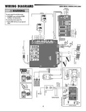
... + DC POWER ACCESSORY POWER + ON- + SW-. LOCK CLASS 2 SUPPLY 24 VOLTS EXP. BOARD BR GRN WT YE BLU RED BR GRN WT YE BLU RED SOLAR / CHARGER + GROUND ID RESET ALARM SET OPEN LED BLINKING OFF BLINKING BLINKING ON ON LIMIT SETUP LEDS SET CLOSE OPERATOR MODE EXPLANATION LED BLINKING NORMAL..., it is recommended that have a variety of the operator, assist with programming, and diagnose potential problems with many LEDs that you unplug the J15 and Solar/Charger plug. Remote controls are set . OFF NORMAL MODE Limits are being erased. 36
... + DC POWER ACCESSORY POWER + ON- + SW-. LOCK CLASS 2 SUPPLY 24 VOLTS EXP. BOARD BR GRN WT YE BLU RED BR GRN WT YE BLU RED SOLAR / CHARGER + GROUND ID RESET ALARM SET OPEN LED BLINKING OFF BLINKING BLINKING ON ON LIMIT SETUP LEDS SET CLOSE OPERATOR MODE EXPLANATION LED BLINKING NORMAL..., it is recommended that have a variety of the operator, assist with programming, and diagnose potential problems with many LEDs that you unplug the J15 and Solar/Charger plug. Remote controls are set . OFF NORMAL MODE Limits are being erased. 36
LA500 Manual
Page 39
... Input active BLINK Input active on other operator OFF Input inactive ON Input active STATUS LEDS INPUT POWER OFF OFF state ON AC charger or Solar power available BATT OFF CHARGING ON Not charging Trickle charge FAST BLINK High current charge FASTER BLINK Over voltage error TIMER OFF The timer is...
... Input active BLINK Input active on other operator OFF Input inactive ON Input active STATUS LEDS INPUT POWER OFF OFF state ON AC charger or Solar power available BATT OFF CHARGING ON Not charging Trickle charge FAST BLINK High current charge FASTER BLINK Over voltage error TIMER OFF The timer is...
LA500 Manual
Page 40
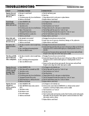
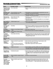
...button is stuck e) Poor radio reception f) Defective control board CORRECTIONS a) Check AC and battery power b) Check fuses c) Charge batteries by AC or solar power or replace batteries d) Replace defective control board a) Use Diagnostic code to identify issue b) Check Reset button c) Check Stop button is not "...stuck on" d) Charges batteries by AC or solar power or replace batteries f) Check all vehicle detector inputs for open or fully close when setting limits. c) Check Stop button is on " ...
...button is stuck e) Poor radio reception f) Defective control board CORRECTIONS a) Check AC and battery power b) Check fuses c) Charge batteries by AC or solar power or replace batteries d) Replace defective control board a) Use Diagnostic code to identify issue b) Check Reset button c) Check Stop button is not "...stuck on" d) Charges batteries by AC or solar power or replace batteries f) Check all vehicle detector inputs for open or fully close when setting limits. c) Check Stop button is on " ...
LA500 Manual
Page 41
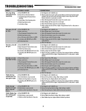
...active input e) Check all vehicle detector inputs for an active detector f) Battery voltage must be 22.0 Vdc or higher. Charge batteries by AC or solar power or replace batteries g) Check Fire Dept input a) Use Diagnostic code to -limit. If no AC power, then running on batteries and battery ...will not open. If no AC power, then running on batteries and battery voltage must be 22.0 Vdc or higher. Charge batteries by AC or solar power or replace batteries a) Check Timer-to open limit. Vehicle Exit loop activation does not cause gate to -Close (TTC) setting b) Check all...
...active input e) Check all vehicle detector inputs for an active detector f) Battery voltage must be 22.0 Vdc or higher. Charge batteries by AC or solar power or replace batteries g) Check Fire Dept input a) Use Diagnostic code to -limit. If no AC power, then running on batteries and battery ...will not open. If no AC power, then running on batteries and battery voltage must be 22.0 Vdc or higher. Charge batteries by AC or solar power or replace batteries a) Check Timer-to open limit. Vehicle Exit loop activation does not cause gate to -Close (TTC) setting b) Check all...
LA500 Manual
Page 42
...low power mode. 40 b) Replace defective edge sensor. If no AC power, then running on batteries (no AC power or solar power available), main board will go into low power mode. Retest that Solenoid has power (do not power maglock from control ...control board is wired to -Operator wireless learning a) Incorrect Bipart switch setting Expansion board function not controlling gate. Charge batteries by AC or solar power or replace batteries a) Check operator-to low power mode. b) Replace defective photoelectric sensor. c) Replace defective expansion board or defective main ...
...low power mode. 40 b) Replace defective edge sensor. If no AC power, then running on batteries (no AC power or solar power available), main board will go into low power mode. Retest that Solenoid has power (do not power maglock from control ...control board is wired to -Operator wireless learning a) Incorrect Bipart switch setting Expansion board function not controlling gate. Charge batteries by AC or solar power or replace batteries a) Check operator-to low power mode. b) Replace defective photoelectric sensor. c) Replace defective expansion board or defective main ...
LA500 Manual
Page 44
... Sensors Field Wiring Edge J5 N O COM N C J15 + BATT - + DC POWER BR GRN WT YE BLU RED BR GRN WT YE BLU RED SOLAR / CHARGER + - LOCK POWER + ON + SW ACCESSORY D RESET ALARM CLA S 2 SU PLY 24 VO TS GROUND EXP BOARD Red Loop Detector Yellow ...: • Replace ONLY with fuse of same type and rating. GROUND Attach to Outlet Metal Chassis With a Single Screw Primary Operator Secondary Operator Two 12V Solar Panels in Series + - + - Black Red 42 N O COM N C N O COM N C LOCK (not provided) Attach to Metal Chassis Solenoid Lock (Optional) LOCK Maglock (...
... Sensors Field Wiring Edge J5 N O COM N C J15 + BATT - + DC POWER BR GRN WT YE BLU RED BR GRN WT YE BLU RED SOLAR / CHARGER + - LOCK POWER + ON + SW ACCESSORY D RESET ALARM CLA S 2 SU PLY 24 VO TS GROUND EXP BOARD Red Loop Detector Yellow ...: • Replace ONLY with fuse of same type and rating. GROUND Attach to Outlet Metal Chassis With a Single Screw Primary Operator Secondary Operator Two 12V Solar Panels in Series + - + - Black Red 42 N O COM N C N O COM N C LOCK (not provided) Attach to Metal Chassis Solenoid Lock (Optional) LOCK Maglock (...
LA500 Manual
Page 45
Secondary Operator Two 12V Solar Panels in Series + - + - For continued protection against fire and electrocution: • DISCONNECT power and battery BEFORE installing or servicing operator. Reset Switch Wire Loop ... CLOSE EYES/ NTERRUPT + + (-) (+) (+) (-) Photoelectric Sensors Photoelectric Sensors J5 N O COM N C J15 + BATT - + DC POWER BR GRN WT YE BLU RED BR GRN WT YE BLU RED SOLAR / CHARGER + - Black Red 43 N O COM N C N O COM N C LOCK (not provided) Attach to Metal Chassis Solenoid Lock (Optional) LOCK Maglock (Optional) (not provided) Red 12V 7AH ...
Secondary Operator Two 12V Solar Panels in Series + - + - For continued protection against fire and electrocution: • DISCONNECT power and battery BEFORE installing or servicing operator. Reset Switch Wire Loop ... CLOSE EYES/ NTERRUPT + + (-) (+) (+) (-) Photoelectric Sensors Photoelectric Sensors J5 N O COM N C J15 + BATT - + DC POWER BR GRN WT YE BLU RED BR GRN WT YE BLU RED SOLAR / CHARGER + - Black Red 43 N O COM N C N O COM N C LOCK (not provided) Attach to Metal Chassis Solenoid Lock (Optional) LOCK Maglock (Optional) (not provided) Red 12V 7AH ...


