LA500 Manual
Page 1
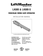
This model is intended for use in Class I, II, III and IV vehicular swing gate applications. LA500 & LA500-S VEHICULAR SWING GATE OPERATOR INSTALLATION MANUAL Your model may look different than the model illustrated in your area. Visit www.liftmaster.com to locate a professional installing dealer in this manual. This model is for use on vehicular passage gates ONLY and not intended for use on pedestrian passage gates. THIS PRODUCT IS TO BE INSTALLED AND SERVICED BY A TRAINED GATE SYSTEMS TECHNICIAN ONLY. UL325 compliant UL991 compliant
This model is intended for use in Class I, II, III and IV vehicular swing gate applications. LA500 & LA500-S VEHICULAR SWING GATE OPERATOR INSTALLATION MANUAL Your model may look different than the model illustrated in your area. Visit www.liftmaster.com to locate a professional installing dealer in this manual. This model is for use on vehicular passage gates ONLY and not intended for use on pedestrian passage gates. THIS PRODUCT IS TO BE INSTALLED AND SERVICED BY A TRAINED GATE SYSTEMS TECHNICIAN ONLY. UL325 compliant UL991 compliant
LA500 Manual
Page 3
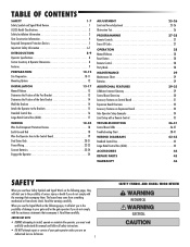
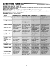
...OPERATION 28 Manual Release 28 Reset Button 28 Remote Control 28 Party Mode 28 MAINTENANCE 29 Maintenance Chart 29 Batteries 29 ADDITIONAL FEATURES 29-35 LiftMaster Internet Gateway 29 Control Board Overview 30 Accessory Features on Control Board 31 Expansion Board Overview 32 Accessory Features on Expansion Board 33 Gate Operator... PARTS 45 WARRANTY 46 SAFETY When you see this manual and follow all safety instructions. • DO NOT attempt repair or service of your gate and/or the gate operator if you do not comply with the cautionary statements that...
...OPERATION 28 Manual Release 28 Reset Button 28 Remote Control 28 Party Mode 28 MAINTENANCE 29 Maintenance Chart 29 Batteries 29 ADDITIONAL FEATURES 29-35 LiftMaster Internet Gateway 29 Control Board Overview 30 Accessory Features on Control Board 31 Expansion Board Overview 32 Accessory Features on Expansion Board 33 Gate Operator... PARTS 45 WARRANTY 46 SAFETY When you see this manual and follow all safety instructions. • DO NOT attempt repair or service of your gate and/or the gate operator if you do not comply with the cautionary statements that...
LA500 Manual
Page 5
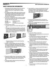
...) must be located at the bottom edge of the gate where easily visible. 11. Reference owner's manual regarding placement of non-contact sensor for the user as well as an edge sensor: a. Vehicular gate systems provide convenience and security. For a gate operator utilizing a non-contact sensor: a. c. Gate operating system designers, installers and users must be supplied with...
...) must be located at the bottom edge of the gate where easily visible. 11. Reference owner's manual regarding placement of non-contact sensor for the user as well as an edge sensor: a. Vehicular gate systems provide convenience and security. For a gate operator utilizing a non-contact sensor: a. c. Gate operating system designers, installers and users must be supplied with...
LA500 Manual
Page 6
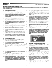
... be constructed in accordance with a powered gate operator. An existing gate latch shall be disabled when a manually operated gate is required to perform their movement shall not be initiated by a swing gate when in the open position or the fully closed positions. Gates shall be automated. 4. SAFETY GATE CONSTRUCTION INFORMATION GATE CONSTRUCTION INFORMATION Vehicular gates should be installed in accordance with...
... be constructed in accordance with a powered gate operator. An existing gate latch shall be disabled when a manually operated gate is required to perform their movement shall not be initiated by a swing gate when in the open position or the fully closed positions. Gates shall be automated. 4. SAFETY GATE CONSTRUCTION INFORMATION GATE CONSTRUCTION INFORMATION Vehicular gates should be installed in accordance with...
LA500 Manual
Page 9
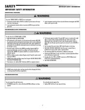
...use ONLY LiftMaster part 29-NP712 for vehicles ONLY. The gate MUST reverse on a separate fused line of adequate capacity. • NEVER let children operate or play with fuse of FIRE or INJURY to persons use separate entrance. • Test the gate operator monthly. MAINTENANCE AND OPERATION •...connected in BOTH the open and close gate cycles. To reduce the risk of INJURY or DEATH. • Use the manual disconnect release ONLY when the gate is properly adjusted and there are no obstructions to gate travel , retest the gate operator. Keep the remote control away from ...
...use ONLY LiftMaster part 29-NP712 for vehicles ONLY. The gate MUST reverse on a separate fused line of adequate capacity. • NEVER let children operate or play with fuse of FIRE or INJURY to persons use separate entrance. • Test the gate operator monthly. MAINTENANCE AND OPERATION •...connected in BOTH the open and close gate cycles. To reduce the risk of INJURY or DEATH. • Use the manual disconnect release ONLY when the gate is properly adjusted and there are no obstructions to gate travel , retest the gate operator. Keep the remote control away from ...
LA500 Manual
Page 11
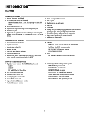
...connection • 3-Button station accessory connection • AUX Relays (2) each independently selectable operation: - Secure power failure selection • SAMS compatible • Slow-start and slow-stop gate motion • Reset Button • Audible Alarm • Standard Control box has an...Adjustable Timer-to pages 20 and 21) • Lockable manual release handle • COMMANDS: - INTEGRATED RADIO RECEIVER: • LOOPS: - CYCLE QUANTITY: LEDs blink operational cycle count 9 PRE-ALERT DELAY: ON 3 seconds before gate motion - Main AC voltage input selection: 120 Vac (...
...connection • 3-Button station accessory connection • AUX Relays (2) each independently selectable operation: - Secure power failure selection • SAMS compatible • Slow-start and slow-stop gate motion • Reset Button • Audible Alarm • Standard Control box has an...Adjustable Timer-to pages 20 and 21) • Lockable manual release handle • COMMANDS: - INTEGRATED RADIO RECEIVER: • LOOPS: - CYCLE QUANTITY: LEDs blink operational cycle count 9 PRE-ALERT DELAY: ON 3 seconds before gate motion - Main AC voltage input selection: 120 Vac (...
LA500 Manual
Page 13
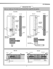
... for Reinforcement (Not provided) 10" Minimum Heavy Steel Bracket (Reinforce if necessary) Back Steel Bracket (Reinforce if necessary) Gate Hinge NOTE: Weld Re Bar Behind Gate Hinges for Maximum Strength. INSTALLATION TYPES Identify your installation type. DUAL GATE Secondary Operator Junction Box ! The installation steps in this manual will show a typical Pull-to-Open application.
... for Reinforcement (Not provided) 10" Minimum Heavy Steel Bracket (Reinforce if necessary) Back Steel Bracket (Reinforce if necessary) Gate Hinge NOTE: Weld Re Bar Behind Gate Hinges for Maximum Strength. INSTALLATION TYPES Identify your installation type. DUAL GATE Secondary Operator Junction Box ! The installation steps in this manual will show a typical Pull-to-Open application.
LA500 Manual
Page 15
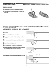
... POSITION OF THE POST BRACKET 1 Close the gate. 2 Choose a vertical mounting location for a Miracle-One™ operator, use the existing post bracket and gate bracket. The operator is Push-to-Open, refer to the illustration to the right. If this operator is a replacement for the post bracket. 3.... 7.75" 8.5" Post Bracket Location 7.75" 8.5" If your application is now in manual mode. PUSH-TO-OPEN 7.75" 8.5" 13 INSTALLATION MANUAL RELEASE + DETERMINE THE POSITION OF THE POST BRACKET MANUAL RELEASE 1 Insert the key into the lock and turn it 180 degrees counterclockwise. 2 ...
... POSITION OF THE POST BRACKET 1 Close the gate. 2 Choose a vertical mounting location for a Miracle-One™ operator, use the existing post bracket and gate bracket. The operator is Push-to-Open, refer to the illustration to the right. If this operator is a replacement for the post bracket. 3.... 7.75" 8.5" Post Bracket Location 7.75" 8.5" If your application is now in manual mode. PUSH-TO-OPEN 7.75" 8.5" 13 INSTALLATION MANUAL RELEASE + DETERMINE THE POSITION OF THE POST BRACKET MANUAL RELEASE 1 Insert the key into the lock and turn it 180 degrees counterclockwise. 2 ...
LA500 Manual
Page 30
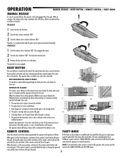
... receiver must be reset: C A. During the open /close cycle, like the gate to shut off the alarm and reset the operator. The next command given by a LiftMaster remote control or SINGLE BUTTON on the gate frame while the gate is in the closed manually. Operator is moving freely. This locks the release lever. 3 Remove the key and...
... receiver must be reset: C A. During the open /close cycle, like the gate to shut off the alarm and reset the operator. The next command given by a LiftMaster remote control or SINGLE BUTTON on the gate frame while the gate is in the closed manually. Operator is moving freely. This locks the release lever. 3 Remove the key and...
LA500 Manual
Page 31
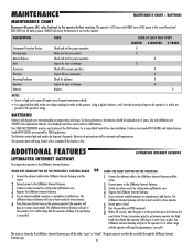
... enabled computer or smartphone to service the operator. DESCRIPTION Entrapment Protection Devices Warning Signs Manual Release Gate Accessories Electrical Mounting Hardware Operator Batteries TASK Check and test for proper operation Make sure they are required for replacement batteries. ADDITIONAL FEATURES LIFTMASTER INTERNET GATEWAY LIFTMASTER INTERNET GATEWAY To program the operator to the LiftMaster Internet Gateway: USING THE LEARN BUTTON...
... enabled computer or smartphone to service the operator. DESCRIPTION Entrapment Protection Devices Warning Signs Manual Release Gate Accessories Electrical Mounting Hardware Operator Batteries TASK Check and test for proper operation Make sure they are required for replacement batteries. ADDITIONAL FEATURES LIFTMASTER INTERNET GATEWAY LIFTMASTER INTERNET GATEWAY To program the operator to the LiftMaster Internet Gateway: USING THE LEARN BUTTON...
LA500 Manual
Page 34
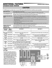
...the AUX relay contact terminal blocks. light). Use this Aux Relay setting to their appropriate positions. To determine the actual cycles that the gate operator has run (in EXIT loop detector faults are ignored (EXIT loop is faulted and inoperative). Cycle count cannot be reset or changed.... DO NOT connect more than 42 Vdc (32 Vac) to the ON setting for 10 seconds, then turn off of close Energizes if gate is manually tampered with barrier gate) Energizes when not at close limit. The Expansion Board's OPEN, CLOSE, and STOP LEDs will turn on for Aux Relay 1. F G...
...the AUX relay contact terminal blocks. light). Use this Aux Relay setting to their appropriate positions. To determine the actual cycles that the gate operator has run (in EXIT loop detector faults are ignored (EXIT loop is faulted and inoperative). Cycle count cannot be reset or changed.... DO NOT connect more than 42 Vdc (32 Vac) to the ON setting for 10 seconds, then turn off of close Energizes if gate is manually tampered with barrier gate) Energizes when not at close limit. The Expansion Board's OPEN, CLOSE, and STOP LEDs will turn on for Aux Relay 1. F G...
LA500 Manual
Page 36
...Relay Out - Normally set to determine operator cycles Typically not required. Normal gate close limit Use during servicing only to BATT. not running on batteries) Attach alert signal (audible or visual alert system) to indicate if gate is manually tampered with by being pushed off of... close limit Use during servicing only to determine operator cycles Connect emergency access system (Knox box switch, SOS system, etc.) Attach visual...
...Relay Out - Normally set to determine operator cycles Typically not required. Normal gate close limit Use during servicing only to BATT. not running on batteries) Attach alert signal (audible or visual alert system) to indicate if gate is manually tampered with by being pushed off of... close limit Use during servicing only to determine operator cycles Connect emergency access system (Knox box switch, SOS system, etc.) Attach visual...
LA500 Manual
Page 40
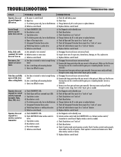
...where the arm mounts to control board. Check operator's antenna and antenna wire. Arm moves, but motor does not run and diagnostic LED not on. Else, replace arm. Correct as needed. Gate must move gate manually. Repair gate as necessary. Replace wireless control as necessary.... c) Check Stop button is on " d) Check Reset button e) Check if similar wired control operates correctly. Correct as needed . Re-learn wireless control...
...where the arm mounts to control board. Check operator's antenna and antenna wire. Arm moves, but motor does not run and diagnostic LED not on. Else, replace arm. Correct as needed. Gate must move gate manually. Repair gate as necessary. Replace wireless control as necessary.... c) Check Stop button is on " d) Check Reset button e) Check if similar wired control operates correctly. Correct as needed . Re-learn wireless control...


