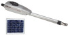
Refer to the solar cycle chart for more details. Manual
Page 1
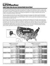
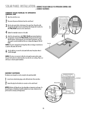
... 50 50 30 Accessories Solenoid Lock(SGLOCK12V) 50 50 27 Loop(LD7LP) 50 50 28 Exit Loop(LM202) 50 50 28 LMGSCCT Cycle rate may require additional solar panels. LA412 Solar Gate Access System Daily Cycle Chart The LA412 Solar Gate Access System utilizes the innovative ...EverCharge® Power Management System to the operator control board. Power is for operating a gate while minimizing power consumption at all other times...
... 50 50 30 Accessories Solenoid Lock(SGLOCK12V) 50 50 27 Loop(LD7LP) 50 50 28 Exit Loop(LM202) 50 50 28 LMGSCCT Cycle rate may require additional solar panels. LA412 Solar Gate Access System Daily Cycle Chart The LA412 Solar Gate Access System utilizes the innovative ...EverCharge® Power Management System to the operator control board. Power is for operating a gate while minimizing power consumption at all other times...
LA412 Manual
Page 2
... 15 15 16 16 17-18 19 WIRING 20-24 Connect the Gate Operator (Gate 1) to the Control Box 20 Set the Lock/Bipart Delay (Model LA412-S Only) 21 Connect the Gate Operator (Gate 2) to the Control Box (Model LA412-S Only) 22 Junction Box (Model LA412-S Only) 23-24 SOLAR PANEL INSTALLATION ADJUSTMENT Limits Force Adjustment Timer-to...
... 15 15 16 16 17-18 19 WIRING 20-24 Connect the Gate Operator (Gate 1) to the Control Box 20 Set the Lock/Bipart Delay (Model LA412-S Only) 21 Connect the Gate Operator (Gate 2) to the Control Box (Model LA412-S Only) 22 Junction Box (Model LA412-S Only) 23-24 SOLAR PANEL INSTALLATION ADJUSTMENT Limits Force Adjustment Timer-to...
LA412 Manual
Page 8
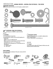
...screws. Quantities are doubled for gate bracket. • The following items are REQUIRED to complete the installation: ALL MODELS: HARDWARE • 5/16" mounting hardware for LA412-S. Post: U-bolt size will call 1-800-528-2806 or visit www.liftmaster.com. standard control box ...3/8" - Hex Nut 5/16"-18 (1) Flat Washer 5/16" (1) Keylock Cap Key (2) Lock Washer 3/8" (3) Flat Washer 3/8" (3) Lock Washer 5/16" (1) Hex Bolt 5/16"-18 ...
...screws. Quantities are doubled for gate bracket. • The following items are REQUIRED to complete the installation: ALL MODELS: HARDWARE • 5/16" mounting hardware for LA412-S. Post: U-bolt size will call 1-800-528-2806 or visit www.liftmaster.com. standard control box ...3/8" - Hex Nut 5/16"-18 (1) Flat Washer 5/16" (1) Keylock Cap Key (2) Lock Washer 3/8" (3) Flat Washer 3/8" (3) Lock Washer 5/16" (1) Hex Bolt 5/16"-18 ...
LA412 Manual
Page 12
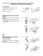
... the gate types and select the type of installation you will require. INSTALLATION » MANUAL RELEASE + DETERMINE POSITION OF THE PULL-TO-OPEN BRACKET + DETERMINE POSITION OF THE "OPTIONAL" PUSH-TO-OPEN BRACKET MANUAL RELEASE 1 Insert the key into the lock and turn it 180° ...counterclockwise. 2 Turn the release lever 180° counterclockwise. The operator is not assembled correctly you will damage the operator. 1 LEFT-HAND GATE RIGHT-HAND GATE Release Lever OR DETERMINE POSITION OF THE "OPTIONAL"...
... the gate types and select the type of installation you will require. INSTALLATION » MANUAL RELEASE + DETERMINE POSITION OF THE PULL-TO-OPEN BRACKET + DETERMINE POSITION OF THE "OPTIONAL" PUSH-TO-OPEN BRACKET MANUAL RELEASE 1 Insert the key into the lock and turn it 180° ...counterclockwise. 2 Turn the release lever 180° counterclockwise. The operator is not assembled correctly you will damage the operator. 1 LEFT-HAND GATE RIGHT-HAND GATE Release Lever OR DETERMINE POSITION OF THE "OPTIONAL"...
LA412 Manual
Page 13
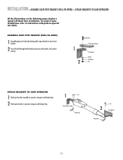
... bracket. 2 Insert the bolt through both brackets and secure with push-to-open installations refer to instructions with washer, lock washer and nut. 1 2 HHexexBoBlto3lt/83"/8" Extension PBurlla-tcok-Oepten Bracket PPoostsBtrBacrkaectket WWaashsehrer LLoockckWaWshaesr her NNuut t ATTACH BRACKETS TO GATE OPERATOR 1 Attach post bracket assembly to operator using pins and hairpin clips. 2 Attach...
... bracket. 2 Insert the bolt through both brackets and secure with push-to-open installations refer to instructions with washer, lock washer and nut. 1 2 HHexexBoBlto3lt/83"/8" Extension PBurlla-tcok-Oepten Bracket PPoostsBtrBacrkaectket WWaashsehrer LLoockckWaWshaesr her NNuut t ATTACH BRACKETS TO GATE OPERATOR 1 Attach post bracket assembly to operator using pins and hairpin clips. 2 Attach...
LA412 Manual
Page 15
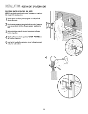
... and nut. 1 3 4 7" (18 cm) 7" (18 cm) Hex Bolt 3/8" 5 Washer Lock Washer Nut 14 Temporarily secure the gate bracket using a clamp. 4 Align the pull-to-open bracket to a position as CLOSE AS POSSIBLE above the screwdriver or dowel rod. 5 Insert hex bolt through...-to-open position (no greater than 100°) and hold operator against gate. 2 Place the operator arm against gate post at the desired position. The gate operator (arm) must be mounted several places on gate for mounting options. 1 Open the gate to desired open bracket and post bracket and secure with clamp. Refer to...
... and nut. 1 3 4 7" (18 cm) 7" (18 cm) Hex Bolt 3/8" 5 Washer Lock Washer Nut 14 Temporarily secure the gate bracket using a clamp. 4 Align the pull-to-open bracket to a position as CLOSE AS POSSIBLE above the screwdriver or dowel rod. 5 Insert hex bolt through...-to-open position (no greater than 100°) and hold operator against gate. 2 Place the operator arm against gate post at the desired position. The gate operator (arm) must be mounted several places on gate for mounting options. 1 Open the gate to desired open bracket and post bracket and secure with clamp. Refer to...
LA412 Manual
Page 16
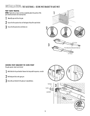
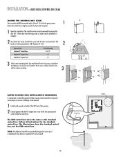
... Washers 3 Hex Nuts Lock Washers 15 2 Carriage Bolts Welder (Optional) Remove the clamp and the operator, set aside. 1 2 Drill adequate holes in the gate post. 3 Secure the post bracket to fully extend or fully retract. 1/2" (1.3 cm) SECURE POST BRACKET TO GATE POST The gate operator (arm) must be... level. 1 Mark holes for the post bracket. INSTALLATION » TEST GATE TRAVEL + SECURE POST BRACKET TO GATE POST TEST GATE TRAVEL NOTE: If gate does not open and close completely adjust the position...
... Washers 3 Hex Nuts Lock Washers 15 2 Carriage Bolts Welder (Optional) Remove the clamp and the operator, set aside. 1 2 Drill adequate holes in the gate post. 3 Secure the post bracket to fully extend or fully retract. 1/2" (1.3 cm) SECURE POST BRACKET TO GATE POST The gate operator (arm) must be... level. 1 Mark holes for the post bracket. INSTALLATION » TEST GATE TRAVEL + SECURE POST BRACKET TO GATE POST TEST GATE TRAVEL NOTE: If gate does not open and close completely adjust the position...
LA412 Manual
Page 17
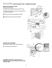
.... 1 Operator Angle Iron OR Wood OR Flat Bar Welder (Optional) Hex Nut Lock Washer Flat Washer 2 Gate Bracket Hex Bolt 3 WARNING SIGN PLACEMENT Warning signs MUST be level. INSTALLATION » SECURE GATE BRACKET TO GATE + WARNING SIGN PLACEMENT SECURE GATE BRACKET TO GATE The gate operator (arm) must use separate entrance Reinforcement Area 3 Manually move at any...
.... 1 Operator Angle Iron OR Wood OR Flat Bar Welder (Optional) Hex Nut Lock Washer Flat Washer 2 Gate Bracket Hex Bolt 3 WARNING SIGN PLACEMENT Warning signs MUST be level. INSTALLATION » SECURE GATE BRACKET TO GATE + WARNING SIGN PLACEMENT SECURE GATE BRACKET TO GATE The gate operator (arm) must use separate entrance Reinforcement Area 3 Manually move at any...
LA412 Manual
Page 20
... BL RD ACCESSORY POWER 12 V BR GR WH YL BL RD GATE 2 LEARN XMITTER ON OFF LOCK / BIPA RT DELAY SET OPEN LIMIT GATE 1 SET CLOSE LIMIT LEARN LIMITS GATE 2 FORCE ON OFF AUTO OPEN LOW BATT OFF MAX ALARM LOCK SOL GND MAGR GATE 1 BR GR WH YL BL RD ACCESSORY POWER 12 V BR...176; Mount the control box as high as the standard control box. ALARM CLOSE EDGE SOL GND OPEN EDGE/ PHOTO MAGR LOCK ON OFF LEARN XMITTER LOCK / BIPA RT DELAY OPEN PHOTO GATE 1 NOTE: BR GR WH YL BL RD TheGATE1 additional CLOSE PHOTO standoffs are specifically designed to mount up to 3 ...
... BL RD ACCESSORY POWER 12 V BR GR WH YL BL RD GATE 2 LEARN XMITTER ON OFF LOCK / BIPA RT DELAY SET OPEN LIMIT GATE 1 SET CLOSE LIMIT LEARN LIMITS GATE 2 FORCE ON OFF AUTO OPEN LOW BATT OFF MAX ALARM LOCK SOL GND MAGR GATE 1 BR GR WH YL BL RD ACCESSORY POWER 12 V BR...176; Mount the control box as high as the standard control box. ALARM CLOSE EDGE SOL GND OPEN EDGE/ PHOTO MAGR LOCK ON OFF LEARN XMITTER LOCK / BIPA RT DELAY OPEN PHOTO GATE 1 NOTE: BR GR WH YL BL RD TheGATE1 additional CLOSE PHOTO standoffs are specifically designed to mount up to 3 ...
LA412 Manual
Page 22
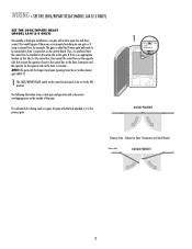
... close second. Thus, it is called the Primary gate and needs to be connected to Gate 1 connections on the control board. WIRING » SET THE LOCK/BIPART DELAY (MODEL LA412-S ONLY) SET THE LOCK/BIPART DELAY (MODEL LA412-S ONLY) Occasionally in dual gate installations, one gate or if using a solenoid lock, for the control box, then mount the control...
... close second. Thus, it is called the Primary gate and needs to be connected to Gate 1 connections on the control board. WIRING » SET THE LOCK/BIPART DELAY (MODEL LA412-S ONLY) SET THE LOCK/BIPART DELAY (MODEL LA412-S ONLY) Occasionally in dual gate installations, one gate or if using a solenoid lock, for the control box, then mount the control...
LA412 Manual
Page 26
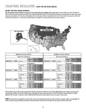
...1 1 10W SOLAR 20W SOLAR 30W SOLAR NUMBER OF CYCLES PER DAY Single Arm Installations 1 PANEL Arm Only 2 PANEL Solenoid Lock Loop LM202 Arm Only 3 PANEL Solenoid Lock Loop LM202 Arm Only Solenoid Lock Loop LM202 Zone 1 Zone 2 50 40 Accessories 50 35 50 31 50 31 50 50 Accessories 50 50 50 50... 7 6 6 20 18 18 18 30 27 28 28 The map (above) and cycles/day ratings are also shown for the entire day. The LA412 Solar Gate Operator is not supported in parallel to three 10W panels (30W total) can be wired in northern climates where temperatures reach below 32° F. If...
...1 1 10W SOLAR 20W SOLAR 30W SOLAR NUMBER OF CYCLES PER DAY Single Arm Installations 1 PANEL Arm Only 2 PANEL Solenoid Lock Loop LM202 Arm Only 3 PANEL Solenoid Lock Loop LM202 Arm Only Solenoid Lock Loop LM202 Zone 1 Zone 2 50 40 Accessories 50 35 50 31 50 31 50 50 Accessories 50 50 50 50... 7 6 6 20 18 18 18 30 27 28 28 The map (above) and cycles/day ratings are also shown for the entire day. The LA412 Solar Gate Operator is not supported in parallel to three 10W panels (30W total) can be wired in northern climates where temperatures reach below 32° F. If...
LA412 Manual
Page 29
... need to connector on the control board. Leave the AC PWR/SOLAR earth ground connection open. Battery Connectors 2 Battery Connection C1Ø1 R182 1 3ØA 32V LOCK D36 SOL GND MAGR D42 Z1 GATE 1 R1 BR GR WH YL BL RD F8 Z12 L1 U4 ON OFF C75 F12 LEARN... LOCK / R2 XMITTER BIPART DELAY D1Ø C7Ø C71 C72 C73 18 GATE 1 K1 SET OPEN LIMIT SET CLOSE LIMIT LEARN LIMITS Control Board GATE 2 TIMER RUNNING Q9 24V R9Ø J2Ø F9 GATE 2 BR R1ØØ GR WH YL BL RD...
... need to connector on the control board. Leave the AC PWR/SOLAR earth ground connection open. Battery Connectors 2 Battery Connection C1Ø1 R182 1 3ØA 32V LOCK D36 SOL GND MAGR D42 Z1 GATE 1 R1 BR GR WH YL BL RD F8 Z12 L1 U4 ON OFF C75 F12 LEARN... LOCK / R2 XMITTER BIPART DELAY D1Ø C7Ø C71 C72 C73 18 GATE 1 K1 SET OPEN LIMIT SET CLOSE LIMIT LEARN LIMITS Control Board GATE 2 TIMER RUNNING Q9 24V R9Ø J2Ø F9 GATE 2 BR R1ØØ GR WH YL BL RD...
LA412 Manual
Page 31
... LIMIT LEDs stop blinking, programming is now complete. (If the SET OPEN LIMIT LED continues to be closed first if there is overlap or a gate lock is overlapping must be exited at any time by pressing the RESET button. PROGRAM OPEN 3 Press the LEARN LIMITS button (SET OPEN LIMIT LED will... beep. LEARN LIMITS button SET OPEN LIMIT R2 K2 U4 D4 D2 RESET BUTTON 4 Press the GATE 1 right button to open the left operator. If the problem continues, see Troubleshooting section.) Test the limits by turning the release lever clockwise 180&#...
... LIMIT LEDs stop blinking, programming is now complete. (If the SET OPEN LIMIT LED continues to be closed first if there is overlap or a gate lock is overlapping must be exited at any time by pressing the RESET button. PROGRAM OPEN 3 Press the LEARN LIMITS button (SET OPEN LIMIT LED will... beep. LEARN LIMITS button SET OPEN LIMIT R2 K2 U4 D4 D2 RESET BUTTON 4 Press the GATE 1 right button to open the left operator. If the problem continues, see Troubleshooting section.) Test the limits by turning the release lever clockwise 180&#...
LA412 Manual
Page 32
...time by turning the release lever clockwise 180°, then turning the key clockwise 180°. GATE 2 may need to move the left button to be closed first if there is overlap or a gate lock is being used. • The programming can be connected to open the right operator. ...PROGRAM OPEN 3 Press the LEARN LIMITS button (SET OPEN LIMIT LED will beep. DIAGNOSTIC GATE 1 SET CLOSE 5 Press the GATE 2 left operator into the OPEN position. ...
...time by turning the release lever clockwise 180°, then turning the key clockwise 180°. GATE 2 may need to move the left button to be closed first if there is overlap or a gate lock is being used. • The programming can be connected to open the right operator. ...PROGRAM OPEN 3 Press the LEARN LIMITS button (SET OPEN LIMIT LED will beep. DIAGNOSTIC GATE 1 SET CLOSE 5 Press the GATE 2 left operator into the OPEN position. ...
LA412 Manual
Page 36
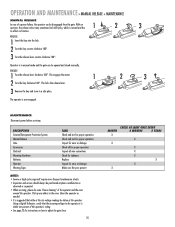
... Insert the key into the lock. 2 Turn the key counter-clockwise 180°. 3 Turn the release lever counter-clockwise 180°. This engages the motor. 1 2 2 Turn the key clockwise 180°. DESCRIPTION External Entrapment Protection System Manual Release Gate Accessories Electrical Mounting Hardware Batteries ... on function. Pick up any debris in a safe place. Clean the operator as needed. • It is suggested that the incoming voltage to adjust the gate force. 35 MONTH X X X CHECK AT LEAST ONCE EVERY 6 MONTHS 3 YEARS X X X X X X Operator is within ten percent of the ...
... Insert the key into the lock. 2 Turn the key counter-clockwise 180°. 3 Turn the release lever counter-clockwise 180°. This engages the motor. 1 2 2 Turn the key clockwise 180°. DESCRIPTION External Entrapment Protection System Manual Release Gate Accessories Electrical Mounting Hardware Batteries ... on function. Pick up any debris in a safe place. Clean the operator as needed. • It is suggested that the incoming voltage to adjust the gate force. 35 MONTH X X X CHECK AT LEAST ONCE EVERY 6 MONTHS 3 YEARS X X X X X X Operator is within ten percent of the ...
LA412 Manual
Page 37
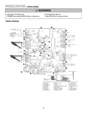
... fuse of same type and rating. 23 1 Fault Alarm Automatic Gate Lock (optional) * 13 BLK RED RED BLK * 12 11 BRN GRN WHT YEL BLU RED Gate 1 (Primary) 10* 12V, 500mA 9 BRN GRN WHT YEL BLU RED Gate 2 (Secondary) 24 ALARM C1Ø1 R182 J19 C66 C65 CLOSE...8 be connected to operate. Antenna Input 2. Control Inputs 7. Force 22. Fuses (20 Amp) 36 Open Photo 5. Loop Inputs 8. Gate 2 10. Lock (Solenoid/Maglock) Output 13. Lock/BiPart Delay 17. Learn Xmitter 18. Alarm Output 14. Timer To Close 23. WIRING DIAGRAM For continued protection against fire: • ...
... fuse of same type and rating. 23 1 Fault Alarm Automatic Gate Lock (optional) * 13 BLK RED RED BLK * 12 11 BRN GRN WHT YEL BLU RED Gate 1 (Primary) 10* 12V, 500mA 9 BRN GRN WHT YEL BLU RED Gate 2 (Secondary) 24 ALARM C1Ø1 R182 J19 C66 C65 CLOSE...8 be connected to operate. Antenna Input 2. Control Inputs 7. Force 22. Fuses (20 Amp) 36 Open Photo 5. Loop Inputs 8. Gate 2 10. Lock (Solenoid/Maglock) Output 13. Lock/BiPart Delay 17. Learn Xmitter 18. Alarm Output 14. Timer To Close 23. WIRING DIAGRAM For continued protection against fire: • ...
LA412 Manual
Page 40
...necessary. • An open and last on an obstruction. GATE DOES NOT CLOSE AUTOMATICALLY WITH TIMER TO CLOSE ENABLED. • Verify that the gate path is starting within the ramp-down distance from the limit. • Lock/Bipart Delay not set . Use a remote control or ... first on open input is properly set . Slide the Lock/Bipart Delay switch to close together. Make sure that Gate 1 starts moving the gate. Check photoelectric sensor for alignment and verify all the time. • The gate is clear of objects. Check connections and operations of safety...
...necessary. • An open and last on an obstruction. GATE DOES NOT CLOSE AUTOMATICALLY WITH TIMER TO CLOSE ENABLED. • Verify that the gate path is starting within the ramp-down distance from the limit. • Lock/Bipart Delay not set . Use a remote control or ... first on open input is properly set . Slide the Lock/Bipart Delay switch to close together. Make sure that Gate 1 starts moving the gate. Check photoelectric sensor for alignment and verify all the time. • The gate is clear of objects. Check connections and operations of safety...
LA412 Manual
Page 43
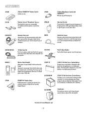
...reduced sunlight and colder weather. LA12VXFMR Push-To-Open Bracket: Used to aOPlElNow the gate operator to integrate with 7 AH battery. The model LA412 is designed to charge the gate operator battery in a small relay type housing so it is housed in place of... strip. To order visit www.liftmaster.com 42 OPEN CLOSE OPEN CLOSE 50-19503 Wireless Gate Doorbell: Allows guests to add a battery for free exit only. SGLOCK12V Automatic Gate Lock: Solenoid-driven lock that automatically unlocks when gate is openOPEN and locks when gate is designed to ring a doorbell...
...reduced sunlight and colder weather. LA12VXFMR Push-To-Open Bracket: Used to aOPlElNow the gate operator to integrate with 7 AH battery. The model LA412 is designed to charge the gate operator battery in a small relay type housing so it is housed in place of... strip. To order visit www.liftmaster.com 42 OPEN CLOSE OPEN CLOSE 50-19503 Wireless Gate Doorbell: Allows guests to add a battery for free exit only. SGLOCK12V Automatic Gate Lock: Solenoid-driven lock that automatically unlocks when gate is openOPEN and locks when gate is designed to ring a doorbell...


