"Manufacturer's Certification for Credit" Manual
Page 1
... LiftMaster LA412 Solar Gate Operator System (Single Gate Model LA412-1PKG) LiftMaster LA412 Solar Gate Operator System (Dual Gate Model LA412-2PKG) LiftMaster SW425DCSP3 Solar Gate Operator System LiftMaster RSL12V Residential DC Slide Gate Operator System ( Single gate model RSL12V) LiftMaster RSL12V Residential DC Slide Gate Operator System ( Dual gate model RSL12V) LiftMaster RSW12V Residential DC Swing Gate Operator System ( Single gate model RSW12V) LiftMaster RSW12V Residential DC Swing Gate Operator System ( Dual gate...
... LiftMaster LA412 Solar Gate Operator System (Single Gate Model LA412-1PKG) LiftMaster LA412 Solar Gate Operator System (Dual Gate Model LA412-2PKG) LiftMaster SW425DCSP3 Solar Gate Operator System LiftMaster RSL12V Residential DC Slide Gate Operator System ( Single gate model RSL12V) LiftMaster RSL12V Residential DC Slide Gate Operator System ( Dual gate model RSL12V) LiftMaster RSW12V Residential DC Swing Gate Operator System ( Single gate model RSW12V) LiftMaster RSW12V Residential DC Swing Gate Operator System ( Dual gate...

Refer to the solar cycle chart for more details. Manual
Page 1
... not included) or extra large control box model LA412CONTXLM (with 33Ah battery) recommended for applications that reach below 32°F. LA412 not supported/available in an open area clear of obstructions and shading for more than 2 consecutive weeks during the winter months.... whether the application is not supported in the given regions. The LA412 is for operating a gate while minimizing power consumption at all other times. LA412 Solar Gate Access System Daily Cycle Chart The LA412 Solar Gate Access System utilizes the innovative EverCharge® Power Management System to...
... not included) or extra large control box model LA412CONTXLM (with 33Ah battery) recommended for applications that reach below 32°F. LA412 not supported/available in an open area clear of obstructions and shading for more than 2 consecutive weeks during the winter months.... whether the application is not supported in the given regions. The LA412 is for operating a gate while minimizing power consumption at all other times. LA412 Solar Gate Access System Daily Cycle Chart The LA412 Solar Gate Access System utilizes the innovative EverCharge® Power Management System to...

LA412 Manual
Page 1
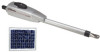
LA412 & LA412-S 12 VOLT DC SOLAR RESIDENTIAL SWING GATE OPERATOR OWNER'S MANUAL MeBtOoLaaxplrtC(giXooennLMatrl)ol FOR RESIDENTIAL USE ONLY ■ Please read this manual and the enclosed safety materials carefully! ■ Periodic checks of the operator by a qualified technician are required to ensure safe operation. ■ The model number is located inside the control box of your operator. ■ Serial # ■ Installation date 2 YEAR WARRANTY
LA412 & LA412-S 12 VOLT DC SOLAR RESIDENTIAL SWING GATE OPERATOR OWNER'S MANUAL MeBtOoLaaxplrtC(giXooennLMatrl)ol FOR RESIDENTIAL USE ONLY ■ Please read this manual and the enclosed safety materials carefully! ■ Periodic checks of the operator by a qualified technician are required to ensure safe operation. ■ The model number is located inside the control box of your operator. ■ Serial # ■ Installation date 2 YEAR WARRANTY
LA412 Manual
Page 2
... 15 15 16 16 17-18 19 WIRING 20-24 Connect the Gate Operator (Gate 1) to the Control Box 20 Set the Lock/Bipart Delay (Model LA412-S Only) 21 Connect the Gate Operator (Gate 2) to the Control Box (Model LA412-S Only) 22 Junction Box (Model LA412-S Only) 23-24 SOLAR PANEL INSTALLATION ADJUSTMENT Limits Force Adjustment Timer...
... 15 15 16 16 17-18 19 WIRING 20-24 Connect the Gate Operator (Gate 1) to the Control Box 20 Set the Lock/Bipart Delay (Model LA412-S Only) 21 Connect the Gate Operator (Gate 2) to the Control Box (Model LA412-S Only) 22 Junction Box (Model LA412-S Only) 23-24 SOLAR PANEL INSTALLATION ADJUSTMENT Limits Force Adjustment Timer...
LA412 Manual
Page 3
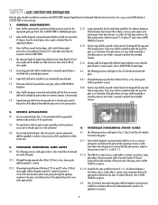
...SAVE THE INSTRUCTIONS. 2 READ and FOLLOW all instructions. 2. The pedestrian access opening and closing to mechanical damage. 12. For a gate operator utilizing a contact sensor such as the bystander. Improperly designed, installed or maintained systems can create risks for vehicles. Controls intended...product manual on the placement of non-contact sensors (photoelectric sensors) for use . Additionally, if the bottom edge of a swing gate is not subject to prevent unauthorized use on the bottom edge. 11. To AVOID damaging gas, power, or other underground utility...
...SAVE THE INSTRUCTIONS. 2 READ and FOLLOW all instructions. 2. The pedestrian access opening and closing to mechanical damage. 12. For a gate operator utilizing a contact sensor such as the bystander. Improperly designed, installed or maintained systems can create risks for vehicles. Controls intended...product manual on the placement of non-contact sensors (photoelectric sensors) for use . Additionally, if the bottom edge of a swing gate is not subject to prevent unauthorized use on the bottom edge. 11. To AVOID damaging gas, power, or other underground utility...
LA412 Manual
Page 4
... shall be guarded or covered. above grade and for barbed wire shall not be less than 6 feet (1.83 m) above grade. 3.1.5 All gates shall be designed with security related parameters specific to not fall over more than is disconnected. Exceptions. 3.2.2 Positive stops shall be required to limit... portion of the adjacent fence that is to be automated shall be upgraded to conform to the provisions of the adjacent fence that time. 4.1.1 Gates shall be designed, constructed and installed so as a wall, pillar or column) covered by gravity when an automatic operator is required to be ...
... shall be guarded or covered. above grade and for barbed wire shall not be less than 6 feet (1.83 m) above grade. 3.1.5 All gates shall be designed with security related parameters specific to not fall over more than is disconnected. Exceptions. 3.2.2 Positive stops shall be required to limit... portion of the adjacent fence that is to be automated shall be upgraded to conform to the provisions of the adjacent fence that time. 4.1.1 Gates shall be designed, constructed and installed so as a wall, pillar or column) covered by gravity when an automatic operator is required to be ...
LA412 Manual
Page 5
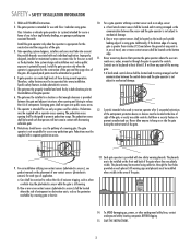
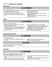
...locating companies BEFORE digging. To reduce the risk of FIRE or INJURY to persons use force adjustments to compensate for a binding or sticking gate. • If one or more than 30W (3 solar panels). SAFETY » IMPORTANT SAFETY INFORMATION INSTALLATION To prevent SERIOUS INJURY or...signs on the front and back of safety reversal system. • NEVER increase force beyond minimum amount required to close gate. • NEVER use ONLY LiftMaster part 29-NP712 for disposal instructions. WIRING To reduce the risk of battery in fire. Battery may also need adjustment....
...locating companies BEFORE digging. To reduce the risk of FIRE or INJURY to persons use force adjustments to compensate for a binding or sticking gate. • If one or more than 30W (3 solar panels). SAFETY » IMPORTANT SAFETY INFORMATION INSTALLATION To prevent SERIOUS INJURY or...signs on the front and back of safety reversal system. • NEVER increase force beyond minimum amount required to close gate. • NEVER use ONLY LiftMaster part 29-NP712 for disposal instructions. WIRING To reduce the risk of battery in fire. Battery may also need adjustment....
LA412 Manual
Page 6
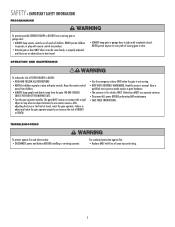
... sensors. Have a qualified service person make repairs to cross path of INJURY or DEATH. • Use the emergency release ONLY when the gate is for vehicles ONLY. For continued protection against fire and electrocution: • DISCONNECT power and battery BEFORE installing or servicing operator. Keep the...; ALWAYS keep people and objects away from children. • ALWAYS keep remote controls out of reach of travel . • ALWAYS keep gate or garage door in sight until completely closed. After adjusting the force or the limit of children. NO ONE SHOULD CROSS THE PATH OF ...
... sensors. Have a qualified service person make repairs to cross path of INJURY or DEATH. • Use the emergency release ONLY when the gate is for vehicles ONLY. For continued protection against fire and electrocution: • DISCONNECT power and battery BEFORE installing or servicing operator. Keep the...; ALWAYS keep people and objects away from children. • ALWAYS keep remote controls out of reach of travel . • ALWAYS keep gate or garage door in sight until completely closed. After adjusting the force or the limit of children. NO ONE SHOULD CROSS THE PATH OF ...
LA412 Manual
Page 7
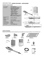
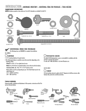
... Watts max. This entrance is for vehicles only Pedestrians must use separate entrance Warning Signs (2) Wire Nuts (6) Model LA412 ONLY Watertight Connector Model LA412-S ONLY (2) Gate Operator Model LA412 (1) Model LA412-S (2) Extension Cable Model LA412-S ONLY 6 Junction Box Model LA412-S ONLY INTRODUCTION » OPERATOR SPECIFICATIONS + CARTON INVENTORY OPERATOR SPECIFICATIONS Main Supply (Motor): Accessory Power: Battery Charger Supply...
... Watts max. This entrance is for vehicles only Pedestrians must use separate entrance Warning Signs (2) Wire Nuts (6) Model LA412 ONLY Watertight Connector Model LA412-S ONLY (2) Gate Operator Model LA412 (1) Model LA412-S (2) Extension Cable Model LA412-S ONLY 6 Junction Box Model LA412-S ONLY INTRODUCTION » OPERATOR SPECIFICATIONS + CARTON INVENTORY OPERATOR SPECIFICATIONS Main Supply (Motor): Accessory Power: Battery Charger Supply...
LA412 Manual
Page 8
...cable between the junction box and the control box. Concrete, Brick, etc.: Four 1/4" x 1-3/4" masonry screws. standard control box 3/8" - LA412-S ONLY: CONDUIT UL Listed outdoor electrical conduit with nut and lock washers. XLM control box PHOTOELECTRIC SENSORS The Model 50-220 photoelectric sensors ... this manual. Quantities are for gate bracket. • The following hardware is needed to complete the installation: ALL MODELS: HARDWARE • 5/16" mounting hardware for LA412. Post: U-bolt size will call 1-800-528-2806 or visit www.liftmaster.com. INTRODUCTION » HARDWARE ...
...cable between the junction box and the control box. Concrete, Brick, etc.: Four 1/4" x 1-3/4" masonry screws. standard control box 3/8" - LA412-S ONLY: CONDUIT UL Listed outdoor electrical conduit with nut and lock washers. XLM control box PHOTOELECTRIC SENSORS The Model 50-220 photoelectric sensors ... this manual. Quantities are for gate bracket. • The following hardware is needed to complete the installation: ALL MODELS: HARDWARE • 5/16" mounting hardware for LA412. Post: U-bolt size will call 1-800-528-2806 or visit www.liftmaster.com. INTRODUCTION » HARDWARE ...
LA412 Manual
Page 9
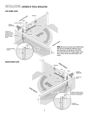
... Bracket Operator Operator Cable Antenna Solar Panel (Facing South) Control Box with Batteries Solar Panel (Facing South) Hinge Post Bracket Gate Bracket PVC Conduit (not provided) to protect the power cable for solar and low voltage wire from lawn mowers and string ...Ground Installation (Optional) 8 Operator Operator Cable Earth Ground Installation (Optional) 11gw22aiWrGueiargeuege (8(282.f4f.te4.metm) ) Photoelectric Sensors RIGHT-HAND GATE NOTE: One or more non-contact sensors shall be exercised to reduce the risk of entrapment or obstruction exists at either the opening...
... Bracket Operator Operator Cable Antenna Solar Panel (Facing South) Control Box with Batteries Solar Panel (Facing South) Hinge Post Bracket Gate Bracket PVC Conduit (not provided) to protect the power cable for solar and low voltage wire from lawn mowers and string ...Ground Installation (Optional) 8 Operator Operator Cable Earth Ground Installation (Optional) 11gw22aiWrGueiargeuege (8(282.f4f.te4.metm) ) Photoelectric Sensors RIGHT-HAND GATE NOTE: One or more non-contact sensors shall be exercised to reduce the risk of entrapment or obstruction exists at either the opening...
LA412 Manual
Page 10
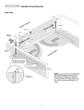
... of nuisance tripping, such as when a vehicle, trips the sensor while the gate is still moving. 9 INSTALLATION » OVERVIEW OF TYPICAL INSTALLATION DUAL GATE Solar Panel (Facing South) Antenna Warning Sign Hinge Post Bracket Gate Bracket Gate 1 Control Box with Batteries Operator Cable Gate 2 Junction Box Extension Cable Photoelectric Sensors PVC Conduit (not provided) to...
... of nuisance tripping, such as when a vehicle, trips the sensor while the gate is still moving. 9 INSTALLATION » OVERVIEW OF TYPICAL INSTALLATION DUAL GATE Solar Panel (Facing South) Antenna Warning Sign Hinge Post Bracket Gate Bracket Gate 1 Control Box with Batteries Operator Cable Gate 2 Junction Box Extension Cable Photoelectric Sensors PVC Conduit (not provided) to...
LA412 Manual
Page 11
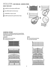
... arm. Minimum distance from the bottom of your gate. RECOMMENDED: = Gate post bracket mounting locations = Gate bracket mount locations OPTIONAL: = Gate post bracket mounting locations = Gate bracket mount locations 10 Gate and gate post MUST be level. INSTALLATION » CHECK YOUR GATE + MOUNTING OPTIONS CHECK YOUR GATE A B A Gate MUST be plumb. B Remove ANY/ALL wheels from the ground should not...
... arm. Minimum distance from the bottom of your gate. RECOMMENDED: = Gate post bracket mounting locations = Gate bracket mount locations OPTIONAL: = Gate post bracket mounting locations = Gate bracket mount locations 10 Gate and gate post MUST be level. INSTALLATION » CHECK YOUR GATE + MOUNTING OPTIONS CHECK YOUR GATE A B A Gate MUST be plumb. B Remove ANY/ALL wheels from the ground should not...
LA412 Manual
Page 12
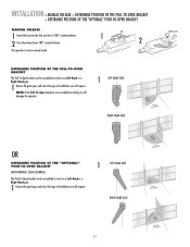
... SEE ACCESSORIES) The Push-To-Open bracket can be assembled to work on a Left-Hand or a Right-Hand gate. 1 Review the gate types and select the type of installation you will require. Key 1 2 DETERMINE POSITION OF THE PULL-TO-OPEN BRACKET The Pull-To-Open bracket can... be assembled to work on a Left-Hand or a Right-Hand gate. 1 Review the gate types and select the type of installation you will damage the operator. 1 LEFT-HAND GATE RIGHT-HAND GATE Release Lever OR DETERMINE POSITION OF THE "OPTIONAL" PUSH-TO-OPEN BRACKET (NOT PROVIDED. NOTE: If...
... SEE ACCESSORIES) The Push-To-Open bracket can be assembled to work on a Left-Hand or a Right-Hand gate. 1 Review the gate types and select the type of installation you will require. Key 1 2 DETERMINE POSITION OF THE PULL-TO-OPEN BRACKET The Pull-To-Open bracket can... be assembled to work on a Left-Hand or a Right-Hand gate. 1 Review the gate types and select the type of installation you will damage the operator. 1 LEFT-HAND GATE RIGHT-HAND GATE Release Lever OR DETERMINE POSITION OF THE "OPTIONAL" PUSH-TO-OPEN BRACKET (NOT PROVIDED. NOTE: If...
LA412 Manual
Page 13
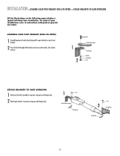
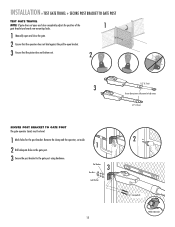
.../83"/8" Extension PBurlla-tcok-Oepten Bracket PPoostsBtrBacrkaectket WWaashsehrer LLoockckWaWshaesr her NNuut t ATTACH BRACKETS TO GATE OPERATOR 1 Attach post bracket assembly to operator using pins and hairpin clips. 2 Attach gate bracket to operator using pins and hairpin clips. 1 Pin Post Bracket Assembly Hairpin Clip... Pin 2 Gate Bracket Hairpin Clip 12 INSTALLATION » ASSEMBLE GATE POST BRACKET (PULL-TO-OPEN) + ATTACH BRACKETS TO GATE OPERATOR All the illustrations on top of post bracket. 2 Insert the bolt ...
.../83"/8" Extension PBurlla-tcok-Oepten Bracket PPoostsBtrBacrkaectket WWaashsehrer LLoockckWaWshaesr her NNuut t ATTACH BRACKETS TO GATE OPERATOR 1 Attach post bracket assembly to operator using pins and hairpin clips. 2 Attach gate bracket to operator using pins and hairpin clips. 1 Pin Post Bracket Assembly Hairpin Clip... Pin 2 Gate Bracket Hairpin Clip 12 INSTALLATION » ASSEMBLE GATE POST BRACKET (PULL-TO-OPEN) + ATTACH BRACKETS TO GATE OPERATOR All the illustrations on top of post bracket. 2 Insert the bolt ...
LA412 Manual
Page 14
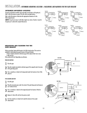
... Measure 7 inches (18 cm) from the previous mark. 5 5 Use the screwdriver or dowel rod to achieve the required dimensions. Gate Post Gate Hinge Point Gate Post Gate Hinge Point Gate Post Gate Hinge Point Operator Hinge Point 7" (18 cm) 7" (18 cm) Operator 7" (18 cm) Hinge Point 7" (18 cm) ...Operator 7" (18 cm) Hinge Point 7" (18 cm) Gate Post Gate Hinge Point Gate Post Gate Hinge Point Gate Post Gate Hinge Point 7" (18 cm) Operator Hinge Point 7" (18 cm) Operator 7" (18 cm) Hinge Point 7" (18 cm) Operator 7" (18 ...
... Measure 7 inches (18 cm) from the previous mark. 5 5 Use the screwdriver or dowel rod to achieve the required dimensions. Gate Post Gate Hinge Point Gate Post Gate Hinge Point Gate Post Gate Hinge Point Operator Hinge Point 7" (18 cm) 7" (18 cm) Operator 7" (18 cm) Hinge Point 7" (18 cm) ...Operator 7" (18 cm) Hinge Point 7" (18 cm) Gate Post Gate Hinge Point Gate Post Gate Hinge Point Gate Post Gate Hinge Point 7" (18 cm) Operator Hinge Point 7" (18 cm) Operator 7" (18 cm) Hinge Point 7" (18 cm) Operator 7" (18 ...
LA412 Manual
Page 15
...cm) Hex Bolt 3/8" 5 Washer Lock Washer Nut 14 The gate operator (arm) must be mounted several places on gate for mounting options. 1 Open the gate to desired open bracket and post bracket and secure with clamp. Temporarily secure the gate bracket using a clamp. 4 Align the pull-to-open bracket...Insert hex bolt through pull-to page 10 for reference. INSTALLATION » POSITION GATE OPERATOR ON GATE POSITION GATE OPERATOR ON GATE NOTE: The post bracket assembly can be level. 2 3 Mark mounting holes on the gate post. Refer to -open position (no greater than 100°) and hold ...
...cm) Hex Bolt 3/8" 5 Washer Lock Washer Nut 14 The gate operator (arm) must be mounted several places on gate for mounting options. 1 Open the gate to desired open bracket and post bracket and secure with clamp. Temporarily secure the gate bracket using a clamp. 4 Align the pull-to-open bracket...Insert hex bolt through pull-to page 10 for reference. INSTALLATION » POSITION GATE OPERATOR ON GATE POSITION GATE OPERATOR ON GATE NOTE: The post bracket assembly can be level. 2 3 Mark mounting holes on the gate post. Refer to -open position (no greater than 100°) and hold ...
LA412 Manual
Page 16
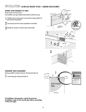
... retract. 1/2" (1.3 cm) SECURE POST BRACKET TO GATE POST The gate operator (arm) must be level. 1 Mark holes for the post bracket. INSTALLATION » TEST GATE TRAVEL + SECURE POST BRACKET TO GATE POST TEST GATE TRAVEL NOTE: If gate does not open and close completely adjust the position ...of the 1 gate bracket and mark new mounting holes. 1 Manually open and close the gate. 2 Ensure that the operator does not...
... retract. 1/2" (1.3 cm) SECURE POST BRACKET TO GATE POST The gate operator (arm) must be level. 1 Mark holes for the post bracket. INSTALLATION » TEST GATE TRAVEL + SECURE POST BRACKET TO GATE POST TEST GATE TRAVEL NOTE: If gate does not open and close completely adjust the position ...of the 1 gate bracket and mark new mounting holes. 1 Manually open and close the gate. 2 Ensure that the operator does not...
LA412 Manual
Page 17
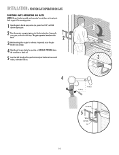
... at any time without prior warning. Do not let children operate the gate or play in gate (or reinforcement, if necessary) that are large enough for the gate bracket mounting hardware. 2 Secure the gate operator to the gate with cable ties. Fence Gate Post 1 Gate Gate Travel Path If installing a 2nd operator, repeat the previous installation steps for...
... at any time without prior warning. Do not let children operate the gate or play in gate (or reinforcement, if necessary) that are large enough for the gate bracket mounting hardware. 2 Secure the gate operator to the gate with cable ties. Fence Gate Post 1 Gate Gate Travel Path If installing a 2nd operator, repeat the previous installation steps for...
LA412 Manual
Page 18
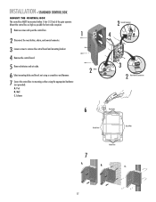
... Outs Knock Outs Knock Outs 7 A. INSTALLATION » STANDARD CONTROL BOX MOUNT THE CONTROL BOX The control box MUST be mounted within 5 feet (1.52 m) of the gate operator.
... Outs Knock Outs Knock Outs 7 A. INSTALLATION » STANDARD CONTROL BOX MOUNT THE CONTROL BOX The control box MUST be mounted within 5 feet (1.52 m) of the gate operator.


