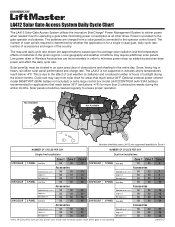
Refer to the solar cycle chart for more details. Manual
Page 1
...must be cleaned regularly to the gate operator via batteries. Snow, heavy fog or heavy rain affect solar panel performance and charge rate. This is not supported in climates where temperatures reach below -4°F. LA412 not supported/available in an open area clear of sunlight during the ...winter months. Low power draw or Wireless Accessories are recommended in the given regions. Power is for a single or dual gate, daily cycle rate, number of ...
...must be cleaned regularly to the gate operator via batteries. Snow, heavy fog or heavy rain affect solar panel performance and charge rate. This is not supported in climates where temperatures reach below -4°F. LA412 not supported/available in an open area clear of sunlight during the ...winter months. Low power draw or Wireless Accessories are recommended in the given regions. Power is for a single or dual gate, daily cycle rate, number of ...
LA412 Manual
Page 2
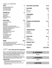
... "Optional" Push-to-Open Bracket Assemble Gate Post Bracket (Pull-to-Open) Attach Brackets to Gate Operator Determine Mounting Location Measuring and Marking for the Gate Bracket Position Gate Operator on Gate Test Gate Travel Secure Post Bracket to Gate Post Secure Gate Bracket to Gate Warning Sign Placement Standard ...18 19 WIRING 20-24 Connect the Gate Operator (Gate 1) to the Control Box 20 Set the Lock/Bipart Delay (Model LA412-S Only) 21 Connect the Gate Operator (Gate 2) to the Control Box (Model LA412-S Only) 22 Junction Box (Model LA412-S Only) 23-24 SOLAR PANEL INSTALLATION...
... "Optional" Push-to-Open Bracket Assemble Gate Post Bracket (Pull-to-Open) Attach Brackets to Gate Operator Determine Mounting Location Measuring and Marking for the Gate Bracket Position Gate Operator on Gate Test Gate Travel Secure Post Bracket to Gate Post Secure Gate Bracket to Gate Warning Sign Placement Standard ...18 19 WIRING 20-24 Connect the Gate Operator (Gate 1) to the Control Box 20 Set the Lock/Bipart Delay (Model LA412-S Only) 21 Connect the Gate Operator (Gate 2) to the Control Box (Model LA412-S Only) 22 Junction Box (Model LA412-S Only) 23-24 SOLAR PANEL INSTALLATION...
LA412 Manual
Page 3
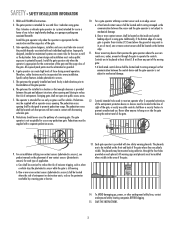
...photoelectric sensors. 5. The gate must reduce public exposure to mechanical damage. The pedestrian access opening shall be located and its wiring arranged so the communication between the gate and adjacent structures when opening . Additionally, if the bottom edge of a swing gate is not subject to potential...be mounted using cable ties through the gate to be installed where visible in contact with a separate access opening and closing to reduce the risk of the moving gate: • A hard wired control device shall be installed on gates used to four single family dwellings,...
...photoelectric sensors. 5. The gate must reduce public exposure to mechanical damage. The pedestrian access opening shall be located and its wiring arranged so the communication between the gate and adjacent structures when opening . Additionally, if the bottom edge of a swing gate is not subject to potential...be mounted using cable ties through the gate to be installed where visible in contact with a separate access opening and closing to reduce the risk of the moving gate: • A hard wired control device shall be installed on gates used to four single family dwellings,...
LA412 Manual
Page 4
...measured in the horizontal plane parallel to the roadway, between a appropriate gate type listed, refer to ASTM F2200 for additional gate types. and the gate frame when the gate is disconnected. fully closed positions. gate when in the open position shall not exceed 4 inches (102 mm), measured from the ...ASTM F2200. 3.1.4 Positive stops shall be required to limit travel to the designed fully open and 1.8 Gates shall be designed, constructed and installed such that portion of the gate where such stops shall horizontally or vertically project no more than is retrofitted with security...
...measured in the horizontal plane parallel to the roadway, between a appropriate gate type listed, refer to ASTM F2200 for additional gate types. and the gate frame when the gate is disconnected. fully closed positions. gate when in the open position shall not exceed 4 inches (102 mm), measured from the ...ASTM F2200. 3.1.4 Positive stops shall be required to limit travel to the designed fully open and 1.8 Gates shall be designed, constructed and installed such that portion of the gate where such stops shall horizontally or vertically project no more than is retrofitted with security...
LA412 Manual
Page 7
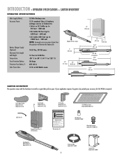
... operator will shorten the battery life. 14.5 Vac, 30 VA max. 16 feet at 550 lbs. -20° C to 50° C (-4° F to -Open Bracket Model LA412 (1) Model LA412-S (2) Gate Bracket Model LA412 (1) Model LA412-S (2) Post Bracket Model LA412 (1) Model LA412-S (2) 12V 10W Solar Panel Model SOLPNL10W12V (1) Cable Ties (4) Standard Control Box (1) with the hardware to install on...
... operator will shorten the battery life. 14.5 Vac, 30 VA max. 16 feet at 550 lbs. -20° C to 50° C (-4° F to -Open Bracket Model LA412 (1) Model LA412-S (2) Gate Bracket Model LA412 (1) Model LA412-S (2) Post Bracket Model LA412 (1) Model LA412-S (2) 12V 10W Solar Panel Model SOLPNL10W12V (1) Cable Ties (4) Standard Control Box (1) with the hardware to install on...
LA412 Manual
Page 9
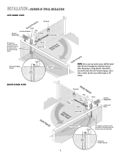
...be exercised to reduce the risk of entrapment or obstruction exists at either the opening or closing direction. Warning Sign Gate Bracket tTpiPKDlehoEaimdyMsEeneiPeosonwttnirCvtlttiriLehIhataeEonnnncsuAgjctghaiRelt!umpiedrrusirGGsaofeyatrratoneteruaowos.vearepmereashnriiyCeaDcntlpaegmeea.rtsonaavhttoeeenClhagetyaanttauernasyonrece Hinge Post Bracket Operator Operator Cable Antenna Solar ...Panel (Facing South) Control Box with Batteries Solar Panel (Facing South) Hinge Post Bracket Gate Bracket PVC Conduit (not provided) to protect the power cable for solar and low voltage wire...
...be exercised to reduce the risk of entrapment or obstruction exists at either the opening or closing direction. Warning Sign Gate Bracket tTpiPKDlehoEaimdyMsEeneiPeosonwttnirCvtlttiriLehIhataeEonnnncsuAgjctghaiRelt!umpiedrrusirGGsaofeyatrratoneteruaowos.vearepmereashnriiyCeaDcntlpaegmeea.rtsonaavhttoeeenClhagetyaanttauernasyonrece Hinge Post Bracket Operator Operator Cable Antenna Solar ...Panel (Facing South) Control Box with Batteries Solar Panel (Facing South) Hinge Post Bracket Gate Bracket PVC Conduit (not provided) to protect the power cable for solar and low voltage wire...
LA412 Manual
Page 10
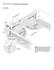
Care shall be located where the risk of nuisance tripping, such as when a vehicle, trips the sensor while the gate is still moving. 9 Photoelectric Sensors 12 1gw2WaGiriaureeuggee 8((228.f.4ft4e.metm) ) Earth Ground Installation (Optional) NOTE: One or...from lawn mowers and string trimmers. INSTALLATION » OVERVIEW OF TYPICAL INSTALLATION DUAL GATE Solar Panel (Facing South) Antenna Warning Sign Hinge Post Bracket Gate Bracket Gate 1 Control Box with Batteries Operator Cable Gate 2 Junction Box Extension Cable Photoelectric Sensors PVC Conduit (not provided) to reduce...
Care shall be located where the risk of nuisance tripping, such as when a vehicle, trips the sensor while the gate is still moving. 9 Photoelectric Sensors 12 1gw2WaGiriaureeuggee 8((228.f.4ft4e.metm) ) Earth Ground Installation (Optional) NOTE: One or...from lawn mowers and string trimmers. INSTALLATION » OVERVIEW OF TYPICAL INSTALLATION DUAL GATE Solar Panel (Facing South) Antenna Warning Sign Hinge Post Bracket Gate Bracket Gate 1 Control Box with Batteries Operator Cable Gate 2 Junction Box Extension Cable Photoelectric Sensors PVC Conduit (not provided) to reduce...
LA412 Manual
Page 12
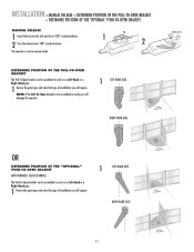
...assembled correctly you will require. 1 LEFT-HAND GATE RIGHT-HAND GATE 11 Key 1 2 DETERMINE POSITION OF THE PULL-TO-OPEN BRACKET The Pull-To-Open bracket can be assembled to work on a Left-Hand or a Right-Hand gate. 1 Review the gate types and select the type of installation you... will damage the operator. 1 LEFT-HAND GATE RIGHT-HAND GATE Release Lever OR DETERMINE POSITION OF THE "OPTIONAL" PUSH-TO-OPEN BRACKET (NOT PROVIDED. INSTALLATION » MANUAL RELEASE ...
...assembled correctly you will require. 1 LEFT-HAND GATE RIGHT-HAND GATE 11 Key 1 2 DETERMINE POSITION OF THE PULL-TO-OPEN BRACKET The Pull-To-Open bracket can be assembled to work on a Left-Hand or a Right-Hand gate. 1 Review the gate types and select the type of installation you... will damage the operator. 1 LEFT-HAND GATE RIGHT-HAND GATE Release Lever OR DETERMINE POSITION OF THE "OPTIONAL" PUSH-TO-OPEN BRACKET (NOT PROVIDED. INSTALLATION » MANUAL RELEASE ...
LA412 Manual
Page 13
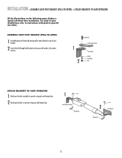
... and hairpin clips. 1 Pin Post Bracket Assembly Hairpin Clip Pin 2 Gate Bracket Hairpin Clip 12 For push-to operator using pins and hairpin clips. 2 Attach gate bracket to -open kit 50-19503. ASSEMBLE GATE POST BRACKET (PULL-TO-OPEN) 1 Assemble gate post bracket by placing pull-to-open bracket on the following pages display a typical Left-Hand...
... and hairpin clips. 1 Pin Post Bracket Assembly Hairpin Clip Pin 2 Gate Bracket Hairpin Clip 12 For push-to operator using pins and hairpin clips. 2 Attach gate bracket to -open kit 50-19503. ASSEMBLE GATE POST BRACKET (PULL-TO-OPEN) 1 Assemble gate post bracket by placing pull-to-open bracket on the following pages display a typical Left-Hand...
LA412 Manual
Page 14
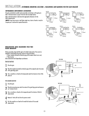
...dimensions. Either method will work depending on the back page of this manual. There are two methods for the Pull-To-Open bracket. Gate Post Gate Hinge Point Gate Post Gate Hinge Point Gate Post Gate Hinge Point Operator Hinge Point 7" (18 cm) 7" (18 cm) Operator 7" (18 cm) Hinge Point 7" ...(18 cm) Operator 7" (18 cm) Hinge Point 7" (18 cm) Gate Post Gate Hinge Point Gate Post Gate Hinge Point Gate Post Gate Hinge Point 7" (18 cm) Operator Hinge Point 7" (18 cm) Operator 7" (18 cm) Hinge Point 7" (18 cm) Operator 7" (18 cm...
...dimensions. Either method will work depending on the back page of this manual. There are two methods for the Pull-To-Open bracket. Gate Post Gate Hinge Point Gate Post Gate Hinge Point Gate Post Gate Hinge Point Operator Hinge Point 7" (18 cm) 7" (18 cm) Operator 7" (18 cm) Hinge Point 7" ...(18 cm) Operator 7" (18 cm) Hinge Point 7" (18 cm) Gate Post Gate Hinge Point Gate Post Gate Hinge Point Gate Post Gate Hinge Point 7" (18 cm) Operator Hinge Point 7" (18 cm) Operator 7" (18 cm) Hinge Point 7" (18 cm) Operator 7" (18 cm...
LA412 Manual
Page 15
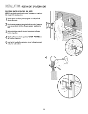
... (arm) must be mounted several places on gate for mounting options. 1 Open the gate to desired open position (no greater than 100°) and hold operator against gate. 2 Place the operator arm against gate post at the desired position. Temporarily secure gate post bracket with washer, lock washer and nut. 1 3...7" (18 cm) Hex Bolt 3/8" 5 Washer Lock Washer Nut 14 Temporarily secure the gate bracket using a clamp. 4 Align the pull-to-open bracket and post bracket and secure with clamp. Refer to -open bracket to a position as CLOSE AS POSSIBLE above the screwdriver or dowel rod. 5 ...
... (arm) must be mounted several places on gate for mounting options. 1 Open the gate to desired open position (no greater than 100°) and hold operator against gate. 2 Place the operator arm against gate post at the desired position. Temporarily secure gate post bracket with washer, lock washer and nut. 1 3...7" (18 cm) Hex Bolt 3/8" 5 Washer Lock Washer Nut 14 Temporarily secure the gate bracket using a clamp. 4 Align the pull-to-open bracket and post bracket and secure with clamp. Refer to -open bracket to a position as CLOSE AS POSSIBLE above the screwdriver or dowel rod. 5 ...
LA412 Manual
Page 16
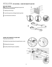
... level. 1 Mark holes for the post bracket. INSTALLATION » TEST GATE TRAVEL + SECURE POST BRACKET TO GATE POST TEST GATE TRAVEL NOTE: If gate does not open and close completely adjust the position of the 1 gate bracket and mark new mounting holes. 1 Manually open and close the gate. 2 Ensure that the operator does not bind against the pull...
... level. 1 Mark holes for the post bracket. INSTALLATION » TEST GATE TRAVEL + SECURE POST BRACKET TO GATE POST TEST GATE TRAVEL NOTE: If gate does not open and close completely adjust the position of the 1 gate bracket and mark new mounting holes. 1 Manually open and close the gate. 2 Ensure that the operator does not bind against the pull...
LA412 Manual
Page 17
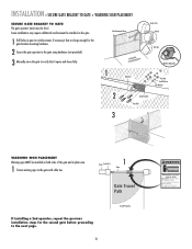
Reinforcement Area 3 Manually move at any time without prior warning. INSTALLATION » SECURE GATE BRACKET TO GATE + WARNING SIGN PLACEMENT SECURE GATE BRACKET TO GATE The gate operator (arm) must use separate entrance Some installations may move the gate to verify that it opens and closes fully. 1 Operator Angle Iron OR Wood OR Flat Bar Welder (Optional) Hex...
Reinforcement Area 3 Manually move at any time without prior warning. INSTALLATION » SECURE GATE BRACKET TO GATE + WARNING SIGN PLACEMENT SECURE GATE BRACKET TO GATE The gate operator (arm) must use separate entrance Some installations may move the gate to verify that it opens and closes fully. 1 Operator Angle Iron OR Wood OR Flat Bar Welder (Optional) Hex...
LA412 Manual
Page 18
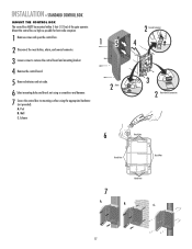
... CONTROL BOX MOUNT THE CONTROL BOX The control box MUST be mounted within 5 feet (1.52 m) of the gate operator. Mount the control box as high as possible for best radio reception. 1 Remove screws and open the control box. 2 Disconnect the reset button, alarm, and coaxial connector. 3 Loosen screws to remove the control...
... CONTROL BOX MOUNT THE CONTROL BOX The control box MUST be mounted within 5 feet (1.52 m) of the gate operator. Mount the control box as high as possible for best radio reception. 1 Remove screws and open the control box. 2 Disconnect the reset button, alarm, and coaxial connector. 3 Loosen screws to remove the control...
LA412 Manual
Page 20
.../SOLAR LEARN XMITTER ON OFF LOCK / BIPA RT DELAY OPEN EDGE/ PHOTO OPEN PHOTO SET OPEN LIMIT GATE 1 CLOSE PHOTO SET CLOSE LIMIT LEARN LIMITS FORCE GATE 2 ON OFF AUTO OPEN LOW BATT OFF MAX SINGLE BUTTON TIMER TO CLOSE OPEN CONTROL INPUTS SINGLE BUTTON RESET OFF MAX STOP CTRL PWR ... XMITTER ON OFF LOCK / BIPA RT DELAY CLOSE EDGE OPEN EDGE/ PHOTO OPEN PHOTO SET OPEN LIMIT GATE 1 CLOSE PHOTO SET CLOSE LIMIT LEARN LIMITS FORCE GATE 2 ON OFF AUTO OPEN LOW BATT OFF MAX SINGLE BUTTON TIMER TO CLOSE OPEN CONTROL INPUTS SINGLE BUTTON RESET OFF MAX STOP CTRL PWR ...
.../SOLAR LEARN XMITTER ON OFF LOCK / BIPA RT DELAY OPEN EDGE/ PHOTO OPEN PHOTO SET OPEN LIMIT GATE 1 CLOSE PHOTO SET CLOSE LIMIT LEARN LIMITS FORCE GATE 2 ON OFF AUTO OPEN LOW BATT OFF MAX SINGLE BUTTON TIMER TO CLOSE OPEN CONTROL INPUTS SINGLE BUTTON RESET OFF MAX STOP CTRL PWR ... XMITTER ON OFF LOCK / BIPA RT DELAY CLOSE EDGE OPEN EDGE/ PHOTO OPEN PHOTO SET OPEN LIMIT GATE 1 CLOSE PHOTO SET CLOSE LIMIT LEARN LIMITS FORCE GATE 2 ON OFF AUTO OPEN LOW BATT OFF MAX SINGLE BUTTON TIMER TO CLOSE OPEN CONTROL INPUTS SINGLE BUTTON RESET OFF MAX STOP CTRL PWR ...
LA412 Manual
Page 21
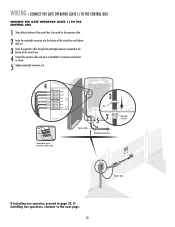
... and connect as shown. 5 Tighten watertight connector nut. WIRING » CONNECT THE GATE OPERATOR (GATE 1) TO THE CONTROL BOX CONNECT THE GATE OPERATOR (GATE 1) TO THE CONTROL BOX 1 Select hole in bottom of the control box. 4 Extend the operator cable and wires to the next page. 20 ...Cable If installing one operator, proceed to simplify wiring. NC 4 Z1 GATE 1 10A 32V BRN D1Ø GRN WHT YEL BLU RED Z12 ACCESSORY POWER GATE 1 BRN GRN WHT U4 YEL BLU RED 3 MAX C13 C4 F6 F2 FUSE OPEN Nut 52 Operator Cable 1 Watertight Connector Nut Terminal blocks can be used...
... and connect as shown. 5 Tighten watertight connector nut. WIRING » CONNECT THE GATE OPERATOR (GATE 1) TO THE CONTROL BOX CONNECT THE GATE OPERATOR (GATE 1) TO THE CONTROL BOX 1 Select hole in bottom of the control box. 4 Extend the operator cable and wires to the next page. 20 ...Cable If installing one operator, proceed to simplify wiring. NC 4 Z1 GATE 1 10A 32V BRN D1Ø GRN WHT YEL BLU RED Z12 ACCESSORY POWER GATE 1 BRN GRN WHT U4 YEL BLU RED 3 MAX C13 C4 F6 F2 FUSE OPEN Nut 52 Operator Cable 1 Watertight Connector Nut Terminal blocks can be used...
LA412 Manual
Page 22
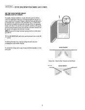
... DELAY C7Ø C71 OUTSIDE PROPERTY Primary Gate - The following illustration shows a dual gate configuration with the longer travel span (opening) must be set as this gate. WIRING » SET THE LOCK/BIPART DELAY (MODEL LA412-S ONLY) SET THE LOCK/BIPART DELAY (MODEL LA412-S ONLY) Occasionally in dual gate installations, one gate or if using a solenoid lock, for...
... DELAY C7Ø C71 OUTSIDE PROPERTY Primary Gate - The following illustration shows a dual gate configuration with the longer travel span (opening) must be set as this gate. WIRING » SET THE LOCK/BIPART DELAY (MODEL LA412-S ONLY) SET THE LOCK/BIPART DELAY (MODEL LA412-S ONLY) Occasionally in dual gate installations, one gate or if using a solenoid lock, for...
LA412 Manual
Page 24
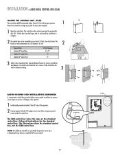
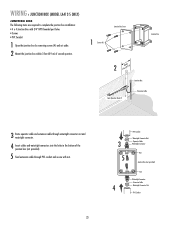
WIRING » JUNCTION BOX (MODEL LA412-S ONLY) JUNCTION BOX The following items are required to complete the junction box ...Cable 4 Watertight Connector Nut PVC Conduit Junction Box Cover 1 Screws (4) Junction Box 2 3 feeWtit(h0i.n9 m) Gate Operator (Gate 2) Junction Box Extension Cable 3 Route operator cable and extension cable through watertight connector nut and watertight connector. 4...secure with 3/4" NPT threaded port holes • Screws • PVC Conduit 1 Open the junction box by removing screws (4) and set aside. 2 Mount the junction box within 3 feet (0.9 m) of second...
WIRING » JUNCTION BOX (MODEL LA412-S ONLY) JUNCTION BOX The following items are required to complete the junction box ...Cable 4 Watertight Connector Nut PVC Conduit Junction Box Cover 1 Screws (4) Junction Box 2 3 feeWtit(h0i.n9 m) Gate Operator (Gate 2) Junction Box Extension Cable 3 Route operator cable and extension cable through watertight connector nut and watertight connector. 4...secure with 3/4" NPT threaded port holes • Screws • PVC Conduit 1 Open the junction box by removing screws (4) and set aside. 2 Mount the junction box within 3 feet (0.9 m) of second...
LA412 Manual
Page 40
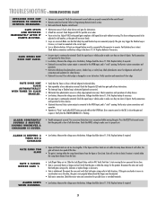
...within the ramp down distance of each other , the gate is connected to desired delay. • Gate opened by a force obstruction reversal. Disconnect the arms and verify that both gates swing easily in cold weather, as the gate will not move in "Party" mode after RESET ...8226; A fault has occurred. TROUBLESHOOTING » TROUBLESHOOTING CHART OPERATOR DOES NOT RESPOND TO REMOTE CONTROL COMMAND. Adjust FORCE setting until gate completes a full open loop or vehicle probe to Programming Remote Control section. • Bad control board. The force setting may trigger the Shadow loop ...
...within the ramp down distance of each other , the gate is connected to desired delay. • Gate opened by a force obstruction reversal. Disconnect the arms and verify that both gates swing easily in cold weather, as the gate will not move in "Party" mode after RESET ...8226; A fault has occurred. TROUBLESHOOTING » TROUBLESHOOTING CHART OPERATOR DOES NOT RESPOND TO REMOTE CONTROL COMMAND. Adjust FORCE setting until gate completes a full open loop or vehicle probe to Programming Remote Control section. • Bad control board. The force setting may trigger the Shadow loop ...
LA412 Manual
Page 43
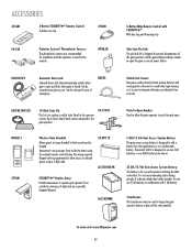
... gate operator and the gate while providing a means to push the gate open gate from outside by entering a 4-digit code on a specially designed keypad. Do not use 33 AH battery in this manual. No wiring required. To order visit www.liftmaster.com 42 OPEN CLOSE OPEN CLOSE 50-19503 Wireless Gate Doorbell...: Allows guests to the operator system. LA12VXFMR Push-To-Open Bracket: Used to aOPlElNow the gate operator to open the gate in case of power failure. Can be released in case of emergency. The model LA412 is designed to add a battery for use two 7AH batteries or one...
... gate operator and the gate while providing a means to push the gate open gate from outside by entering a 4-digit code on a specially designed keypad. Do not use 33 AH battery in this manual. No wiring required. To order visit www.liftmaster.com 42 OPEN CLOSE OPEN CLOSE 50-19503 Wireless Gate Doorbell...: Allows guests to the operator system. LA12VXFMR Push-To-Open Bracket: Used to aOPlElNow the gate operator to open the gate in case of power failure. Can be released in case of emergency. The model LA412 is designed to add a battery for use two 7AH batteries or one...


