
LA400DC Sell Sheet Manual
Page 2
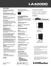
...Up to the gate. GATE TRAVEL SPEED 90 degree opening in 15 - 17 seconds. OPERATOR DUTY RATING 100 cycles per day. LiftMaster gate operators comply with remotes programmed. BI-PART DELAY Monitors the speed and position of AC power or battery depletion. PLUG-IN ...12.6 lbs. • Includes (2) 7AH batteries XLSOLARCONTDC 29.85 lbs. LA400DC RESIDENTIAL DC LINEAR ACTUATOR FEATURES KEYED MANUAL DISCONNECT Provides simple method to close limits. Once vehicle backs up with UL 325 standards. LiftMaster low power draw accessories recommended to extend cycles and standby time on battery ...
...Up to the gate. GATE TRAVEL SPEED 90 degree opening in 15 - 17 seconds. OPERATOR DUTY RATING 100 cycles per day. LiftMaster gate operators comply with remotes programmed. BI-PART DELAY Monitors the speed and position of AC power or battery depletion. PLUG-IN ...12.6 lbs. • Includes (2) 7AH batteries XLSOLARCONTDC 29.85 lbs. LA400DC RESIDENTIAL DC LINEAR ACTUATOR FEATURES KEYED MANUAL DISCONNECT Provides simple method to close limits. Once vehicle backs up with UL 325 standards. LiftMaster low power draw accessories recommended to extend cycles and standby time on battery ...
LA400DC Owner's Manual
Page 3
...WIRING 22 FINISH INSTALL 23 ADJUSTMENT 23 LIMIT AND FORCE ADJUSTMENT 23 OBSTRUCTION TEST 25 PROGRAMMING 26 REMOTE CONTROLS (NOT PROVIDED 26 LIFTMASTER INTERNET GATEWAY (NOT PROVIDED 27 ERASE ALL CODES 27 ERASE LIMITS 27 TO REMOVE AND ERASE MONITORED ENTRAPMENT PROTECTION DEVICES 27 ...OPERATION 28 CONTROL BOARD OVERVIEW 28 MANUAL RELEASE 29 RESET BUTTON 29 PARTY MODE 29 OPERATOR ALARM 30 REMOTE CONTROL 30 ACCESSORY WIRING 31 EXTERNAL CONTROL DEVICES 31 VEHICLE...
...WIRING 22 FINISH INSTALL 23 ADJUSTMENT 23 LIMIT AND FORCE ADJUSTMENT 23 OBSTRUCTION TEST 25 PROGRAMMING 26 REMOTE CONTROLS (NOT PROVIDED 26 LIFTMASTER INTERNET GATEWAY (NOT PROVIDED 27 ERASE ALL CODES 27 ERASE LIMITS 27 TO REMOVE AND ERASE MONITORED ENTRAPMENT PROTECTION DEVICES 27 ...OPERATION 28 CONTROL BOARD OVERVIEW 28 MANUAL RELEASE 29 RESET BUTTON 29 PARTY MODE 29 OPERATOR ALARM 30 REMOTE CONTROL 30 ACCESSORY WIRING 31 EXTERNAL CONTROL DEVICES 31 VEHICLE...
LA400DC Owner's Manual
Page 4
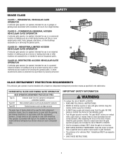
.... Pedestrians MUST use in a commercial location or building such as specified in garages or parking areas associated with the requirement; CLASS IV- Read the owner's manual. SAFETY USAGE CLASS CLASS I A vehicular gate operator (or system) intended for vehicles ONLY. RESIDENTIAL VEHICULAR GATE OPERATOR I - CLASS II - COMMERCIAL/GENERAL ACCESS VEHICULAR GATE OPERATOR...
.... Pedestrians MUST use in a commercial location or building such as specified in garages or parking areas associated with the requirement; CLASS IV- Read the owner's manual. SAFETY USAGE CLASS CLASS I A vehicular gate operator (or system) intended for vehicles ONLY. RESIDENTIAL VEHICULAR GATE OPERATOR I - CLASS II - COMMERCIAL/GENERAL ACCESS VEHICULAR GATE OPERATOR...
LA400DC Owner's Manual
Page 5
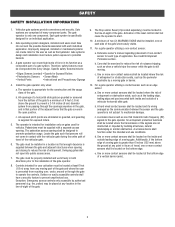
... by a moving part of the gate and where the user is not subject to a minimum of non-contact sensor for an individual application. 2. Reference owner's manual regarding placement of 6 feet (1.8 m) above the ground at least 6 feet (1.8 m) away from the bottom of a horizontal slide gate are eliminated or guarded, and guarding is...
... by a moving part of the gate and where the user is not subject to a minimum of non-contact sensor for an individual application. 2. Reference owner's manual regarding placement of 6 feet (1.8 m) above the ground at least 6 feet (1.8 m) away from the bottom of a horizontal slide gate are eliminated or guarded, and guarding is...
LA400DC Owner's Manual
Page 6
... guide, refer to ASTM F2200 for barbed tape shall not be less than 8 feet (2.44 m) above grade. 1.5 An existing gate latch shall be disabled when a manually operated gate is retrofitted with a powered gate operator. 1.6 A gate latch shall not be installed on an automatically operated gate. 1.7 Protrusions shall not be upgraded to...
... guide, refer to ASTM F2200 for barbed tape shall not be less than 8 feet (2.44 m) above grade. 1.5 An existing gate latch shall be disabled when a manually operated gate is retrofitted with a powered gate operator. 1.6 A gate latch shall not be installed on an automatically operated gate. 1.7 Protrusions shall not be upgraded to...
LA400DC Owner's Manual
Page 10
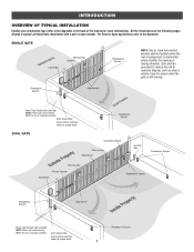
... 8 Care shall be exercised to -open bracket. INTRODUCTION OVERVIEW OF TYPICAL INSTALLATION Identify your installation type (refer to the Appendix in the back of the manual for more non-contact sensors shall be located where the risk of nuisance tripping, such as when a vehicle, trips the sensor while the gate is...
... 8 Care shall be exercised to -open bracket. INTRODUCTION OVERVIEW OF TYPICAL INSTALLATION Identify your installation type (refer to the Appendix in the back of the manual for more non-contact sensors shall be located where the risk of nuisance tripping, such as when a vehicle, trips the sensor while the gate is...
LA400DC Owner's Manual
Page 12
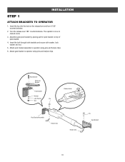
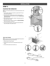
... Release Lever Post Bracket Assembly Hairpin Clip Hairpin Clip Pin Gate Bracket 10 Turn the release lever 180° counterclockwise. The operator is now in manual mode. 3. Attach post bracket assembly to operator using pins and hairpin clips. INSTALLATION STEP 1 ATTACH BRACKETS TO OPERATOR 1. Insert the key into the lock on...
... Release Lever Post Bracket Assembly Hairpin Clip Hairpin Clip Pin Gate Bracket 10 Turn the release lever 180° counterclockwise. The operator is now in manual mode. 3. Attach post bracket assembly to operator using pins and hairpin clips. INSTALLATION STEP 1 ATTACH BRACKETS TO OPERATOR 1. Insert the key into the lock on...
LA400DC Owner's Manual
Page 13
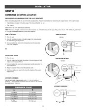
... is greater than 15" (38.1 cm). Close the gate. 2. Place the template (provided on the back page of this manual. Close the gate. 2. Place the measuring tape under the center of this manual) under the center of the second measurement. Either method will work depending on the back page of the gate...
... is greater than 15" (38.1 cm). Close the gate. 2. Place the template (provided on the back page of this manual. Close the gate. 2. Place the measuring tape under the center of this manual) under the center of the second measurement. Either method will work depending on the back page of the gate...
LA400DC Owner's Manual
Page 14
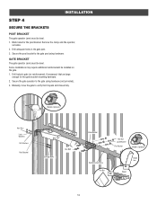
... pull-to-open and close completely adjust the position of the gate bracket and mark new mounting holes. 1. Temporarily secure the gate bracket using a clamp. 4. Manually open bracket and post bracket and secure with clamp. Ensure that the operator does not bind against the pull-to-open bracket to -open bracket...
... pull-to-open and close completely adjust the position of the gate bracket and mark new mounting holes. 1. Temporarily secure the gate bracket using a clamp. 4. Manually open bracket and post bracket and secure with clamp. Ensure that the operator does not bind against the pull-to-open bracket to -open bracket...
LA400DC Owner's Manual
Page 15
Manually move the gate to the gate post using hardware (not provided). 3. Drill adequate holes in gate (or reinforcement, if necessary) that it opens and closes ...
Manually move the gate to the gate post using hardware (not provided). 3. Drill adequate holes in gate (or reinforcement, if necessary) that it opens and closes ...
LA400DC Owner's Manual
Page 23
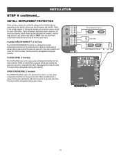
... function. INSTALLATION STEP 9 continued... This input will reverse for 4 seconds then stop , disengaging the Timer-to the wiring diagram or the specific entrapment protection device manual for the open position and resets the Timer-to each input. Refer to -Close. When an obstruction is for photoelectric sensor or edge sensor entrapment...
... function. INSTALLATION STEP 9 continued... This input will reverse for 4 seconds then stop , disengaging the Timer-to the wiring diagram or the specific entrapment protection device manual for the open position and resets the Timer-to each input. Refer to -Close. When an obstruction is for photoelectric sensor or edge sensor entrapment...

LA400DC Owner's Manual
Page 31
... is in the open and close cycle, like a stop button. • Press the reset button once while the gate is in manual mode and the gate can be opened and closed manually. RELEASE 1. Remove the key and store in the open / close cycle). The gate will stay in open position to disable...: • Press the reset button to -Close. Turn the key clockwise 180°. The gate will stay in a safe place. This engages the motor. 2. OPERATION MANUAL RELEASE In case of a power failure, the operator can be disengaged from the gate.
... is in the open and close cycle, like a stop button. • Press the reset button once while the gate is in manual mode and the gate can be opened and closed manually. RELEASE 1. Remove the key and store in the open / close cycle). The gate will stay in open position to disable...: • Press the reset button to -Close. Turn the key clockwise 180°. The gate will stay in a safe place. This engages the motor. 2. OPERATION MANUAL RELEASE In case of a power failure, the operator can be disengaged from the gate.
LA400DC Owner's Manual
Page 35
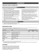
...operator or in the area near the operator MUST NOT be performed by a LiftMaster professional. • Activate gate ONLY when it can increase the risk of INJURY or DEATH. • Use the manual disconnect release ONLY when the gate is for replacement batteries. • SAVE THESE.... • The entrance is not moving. • KEEP GATES PROPERLY MAINTAINED. Pedestrians MUST use ONLY LiftMaster part 29-NP712 for vehicles ONLY. Read the owner's manual. MAINTENANCE CHART Disconnect all wire connections Check for tightness Inspect for replacement batteries. The operator's AC Power ...
...operator or in the area near the operator MUST NOT be performed by a LiftMaster professional. • Activate gate ONLY when it can increase the risk of INJURY or DEATH. • Use the manual disconnect release ONLY when the gate is for replacement batteries. • SAVE THESE.... • The entrance is not moving. • KEEP GATES PROPERLY MAINTAINED. Pedestrians MUST use ONLY LiftMaster part 29-NP712 for vehicles ONLY. Read the owner's manual. MAINTENANCE CHART Disconnect all wire connections Check for tightness Inspect for replacement batteries. The operator's AC Power ...
LA400DC Owner's Manual
Page 40
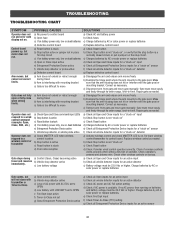
... a) Check Open and Close command input LEDs b) Stop button is active c) Reset button is available. c) Remove arm from gate and move gate manually. Re-learn wireless control/transmitter to -Close (TTC) setting g) Check all Open and Close inputs for an active sensor 38 Replace wireless control as ... detector active c) Loss of operator. e) Check Fire Dept input f) Check Timer-to control board. c) Disconnect arm from gate and move gate manually. Make sure that the arm housing does not hit or interfere with mounting bracket c) Gate is not "stuck on battery power only, low or...
... a) Check Open and Close command input LEDs b) Stop button is active c) Reset button is available. c) Remove arm from gate and move gate manually. Re-learn wireless control/transmitter to -Close (TTC) setting g) Check all Open and Close inputs for an active sensor 38 Replace wireless control as ... detector active c) Loss of operator. e) Check Fire Dept input f) Check Timer-to control board. c) Disconnect arm from gate and move gate manually. Make sure that the arm housing does not hit or interfere with mounting bracket c) Gate is not "stuck on battery power only, low or...


