HS670 GL BOARD Manual
Page 2
... Warning Sign Placement 8 CARTON INVENTORY INSTALLATION Concrete Pad 9 Drive Rail 9 Operator Mounting 9 Vent Cap 10 Limit Shoes 10 Gate Stops 11 Suspension System 11 Manual Operation 11 WIRING Power Wiring Installation 12 On/Off Switch Power Wiring 13 ADJUSTMENT RPM...1 OPTIONAL CONTROL DEVICES Sequenced Access Management System (SAMS 20 WARNING Accessory Wiring 21 Control Connection Diagrams 22 Mechanical OPERATION AND MAINTENANCE CAUTION WARNING Important Safety Instructions 23 TROUBLESHOOTING CAUTION GL Board Features 24 Electrical Troubleshooting 25-26 Hydraulic ...
... Warning Sign Placement 8 CARTON INVENTORY INSTALLATION Concrete Pad 9 Drive Rail 9 Operator Mounting 9 Vent Cap 10 Limit Shoes 10 Gate Stops 11 Suspension System 11 Manual Operation 11 WIRING Power Wiring Installation 12 On/Off Switch Power Wiring 13 ADJUSTMENT RPM...1 OPTIONAL CONTROL DEVICES Sequenced Access Management System (SAMS 20 WARNING Accessory Wiring 21 Control Connection Diagrams 22 Mechanical OPERATION AND MAINTENANCE CAUTION WARNING Important Safety Instructions 23 TROUBLESHOOTING CAUTION GL Board Features 24 Electrical Troubleshooting 25-26 Hydraulic ...

HS670 GL BOARD Manual
Page 3
...polyurethane material on during operator operation. G. LIMIT SWITCH All limit switches are T.E.F.C. (totally enclosed, fan cooled) and operate at 600 p.s.i. H. J. MOTOR 1 AND 2 HP The motors used in manually resettable thermal overload. B. The power required for HS670 1HP and 1500 p.s.i....MOTOR Roller vane, free wheeling type with a displacement of NEMA 3, 4, and 13 construction. When positioned downward, it will allow manual operation of pump. for operation is 3 position, 4 way. HS670 1HP = 1-1/2" wide, 6" diameter; BYPASS VALVE Incorporates a handle at side of the gate...
...polyurethane material on during operator operation. G. LIMIT SWITCH All limit switches are T.E.F.C. (totally enclosed, fan cooled) and operate at 600 p.s.i. H. J. MOTOR 1 AND 2 HP The motors used in manually resettable thermal overload. B. The power required for HS670 1HP and 1500 p.s.i....MOTOR Roller vane, free wheeling type with a displacement of NEMA 3, 4, and 13 construction. When positioned downward, it will allow manual operation of pump. for operation is 3 position, 4 way. HS670 1HP = 1-1/2" wide, 6" diameter; BYPASS VALVE Incorporates a handle at side of the gate...
HS670 GL BOARD Manual
Page 6
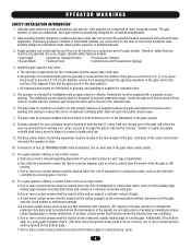
... transmission of non-contact sensor for user activation must take into account the possible hazards associated with a separate access opening. Install the gate operator only when: a. Reference owner's manual regarding placement of the signals are not obstructed or impeded by a moving gate or barrier. 12. c. A wireless contact sensor such as the one...
... transmission of non-contact sensor for user activation must take into account the possible hazards associated with a separate access opening. Install the gate operator only when: a. Reference owner's manual regarding placement of the signals are not obstructed or impeded by a moving gate or barrier. 12. c. A wireless contact sensor such as the one...
HS670 GL BOARD Manual
Page 10
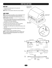
NOTE: Never run the operator without the vent cap installed. These items are slotted, so minor adjustments may be made later for installation instructions. Locate the open the gate about ... Limit Switch Top View 1-1/16" Side View 2" 3" 1/4"-20 Screw Limit Shoe Centerline Marks Limit Switch 2" 9/32" Dia. 3" Holes Washer and Nut Bottom of drive rail. Manually open and close position. 5. Install the vent cap. I N S TA L L AT I O N VENT CAP 1. Cut wire ties to release limit switch levers and RPM assembly to the...
NOTE: Never run the operator without the vent cap installed. These items are slotted, so minor adjustments may be made later for installation instructions. Locate the open the gate about ... Limit Switch Top View 1-1/16" Side View 2" 3" 1/4"-20 Screw Limit Shoe Centerline Marks Limit Switch 2" 9/32" Dia. 3" Holes Washer and Nut Bottom of drive rail. Manually open and close position. 5. Install the vent cap. I N S TA L L AT I O N VENT CAP 1. Cut wire ties to release limit switch levers and RPM assembly to the...

HS670 GL BOARD Manual
Page 11
... get the gate started . NOTE: A back-up to pinch the drive rail. IMPORTANT: If using the LiftMaster drive rail, make sure that the suspension system is positioned properly. MANUAL OPERATION NOTE: When manually opening or closing the gate, it is the suspension separator bolt. I N S TA L L AT ...pressure is equipped with LiftMaster Drive Rail) Upper Drive Wheel Drive Rail Guide Wheel Lower Drive Wheel Bypass Valve Handle In Automatic Position Rotate 90° (Down) For Manual Operation 11 By tightening this slightly for use with a manual bypass valve. When ...
... get the gate started . NOTE: A back-up to pinch the drive rail. IMPORTANT: If using the LiftMaster drive rail, make sure that the suspension system is positioned properly. MANUAL OPERATION NOTE: When manually opening or closing the gate, it is the suspension separator bolt. I N S TA L L AT ...pressure is equipped with LiftMaster Drive Rail) Upper Drive Wheel Drive Rail Guide Wheel Lower Drive Wheel Bypass Valve Handle In Automatic Position Rotate 90° (Down) For Manual Operation 11 By tightening this slightly for use with a manual bypass valve. When ...
HS670 GL BOARD Manual
Page 22
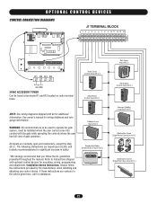
... 24 VAC 24VAC ACCESSORY POWER Can be installed where the user cannot come into contact with the gate while operating the controls where the user has full view of gate operation. See owner's manual for mounting, wiring, programming and adjustment. Refer to the advice given here, call for additional information. The following instructions...
... 24 VAC 24VAC ACCESSORY POWER Can be installed where the user cannot come into contact with the gate while operating the controls where the user has full view of gate operation. See owner's manual for mounting, wiring, programming and adjustment. Refer to the advice given here, call for additional information. The following instructions...
HS670 GL BOARD Manual
Page 23
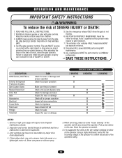
... NOTES: 1. When servicing, please do some "house cleaning" of travel, retest the gate operator. 9. It is suggested that the incoming voltage to be performed by a LiftMaster SEMENT AVERTISSEMENT Failure to gate hardware. The entrance is not 2. on contact with gate controls....CROSS THE PATH OF THE MOVING repairs to adjust and retest the gate operator properly professional. Severe or high cycle usage will require more frequent maintenance checks. 2. owner's manual. ION AVERTISSEMENT DESCRIPTION RPM Sensor (Hall Effect) External Entrapment Protection Systems ...
... NOTES: 1. When servicing, please do some "house cleaning" of travel, retest the gate operator. 9. It is suggested that the incoming voltage to be performed by a LiftMaster SEMENT AVERTISSEMENT Failure to gate hardware. The entrance is not 2. on contact with gate controls....CROSS THE PATH OF THE MOVING repairs to adjust and retest the gate operator properly professional. Severe or high cycle usage will require more frequent maintenance checks. 2. owner's manual. ION AVERTISSEMENT DESCRIPTION RPM Sensor (Hall Effect) External Entrapment Protection Systems ...

HS670 GL BOARD Manual
Page 25
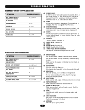
... humming, grinding or making good contact with the pins on page 12 of this manual. ➤ Perform a visual inspection of the motor. Remove the wires from the panel. TROUBLESHOOTING FAULT POSSIBLE CAUSE FIX OPERATOR FAILS TO RUN 1) No stop control has been installed across terminals TB1-3 and TB1... tap is in a dual gate configuration, make sure factory plug-in voltage. If all accessory devices and test the operator. Make sure that the proper wire gauge was used on page 12 of this manual. If fuse and tap are installed on , check the corresponding input. If...
... humming, grinding or making good contact with the pins on page 12 of this manual. ➤ Perform a visual inspection of the motor. Remove the wires from the panel. TROUBLESHOOTING FAULT POSSIBLE CAUSE FIX OPERATOR FAILS TO RUN 1) No stop control has been installed across terminals TB1-3 and TB1... tap is in a dual gate configuration, make sure factory plug-in voltage. If all accessory devices and test the operator. Make sure that the proper wire gauge was used on page 12 of this manual. If fuse and tap are installed on , check the corresponding input. If...

HS670 GL BOARD Manual
Page 26
... in the same conduit with any subsequent programming changes will indicate the activation of phase (three phase only). OPERATOR STOPS AND ALARMS 1) Operator's manual release is engaged. 2) Operator's main power is not engaged. See page 11. ➤ Turn off , make sure factory plug-in... not gate edges. If the wheels slip on . OPERATOR OPENS 1) Active or malfunctioning accessory IMMEDIATELY UPON check the red input status LEDs, POWER UP AND DOES NOT D11-D13 CLOSE OPERATOR HAS TROUBLE 1) Operator's manual release is engaged LEARNING THE MOTOR PROGRAMMING CHANGES 1) Check...
... in the same conduit with any subsequent programming changes will indicate the activation of phase (three phase only). OPERATOR STOPS AND ALARMS 1) Operator's manual release is engaged. 2) Operator's main power is not engaged. See page 11. ➤ Turn off , make sure factory plug-in... not gate edges. If the wheels slip on . OPERATOR OPENS 1) Active or malfunctioning accessory IMMEDIATELY UPON check the red input status LEDs, POWER UP AND DOES NOT D11-D13 CLOSE OPERATOR HAS TROUBLE 1) Operator's manual release is engaged LEARNING THE MOTOR PROGRAMMING CHANGES 1) Check...
HS670 GL BOARD Manual
Page 27
... 29. (G) SEALS: (H) RELIEF VALVE: See page 29. (I ) SPRINGS: Check for interference with the drive rail. (F) OPERATOR MOUNTING: Make sure operator is fastened to dissipate. Check the spring tension. Check fluid level. (C) DIRECTION VALVE: Press and hold the manual override button on one of limit shoes. (I ) FLUID: Check fluid level in the system, allow...
... 29. (G) SEALS: (H) RELIEF VALVE: See page 29. (I ) SPRINGS: Check for interference with the drive rail. (F) OPERATOR MOUNTING: Make sure operator is fastened to dissipate. Check the spring tension. Check fluid level. (C) DIRECTION VALVE: Press and hold the manual override button on one of limit shoes. (I ) FLUID: Check fluid level in the system, allow...

HS670 GL BOARD Manual
Page 28
...C1 P R.V. Double arrowheads designate bi-directional. 3. Reference hydraulic circuit. The speed of 2250 and a rated burst P.S.I . for manual operation, it will redirect the fluid back into the tank until it is full, the fluidmark should exceed its factory setting, it will... bleed off the excess. x 6" dia.) HS670 2HP (2" w. NOTES: 1. Circumference of approximately 70 "A" shore. Directional Valve M.V. T.S. should be free wheeling. Both models have a hardness...
...C1 P R.V. Double arrowheads designate bi-directional. 3. Reference hydraulic circuit. The speed of 2250 and a rated burst P.S.I . for manual operation, it will redirect the fluid back into the tank until it is full, the fluidmark should exceed its factory setting, it will... bleed off the excess. x 6" dia.) HS670 2HP (2" w. NOTES: 1. Circumference of approximately 70 "A" shore. Directional Valve M.V. T.S. should be free wheeling. Both models have a hardness...
HS670 GL BOARD Manual
Page 29
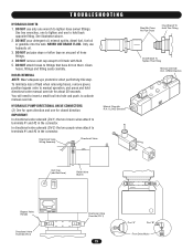
...open direction and one for about 30 seconds. In directional valve solenoid (DV-2) the two purple wires attach to hold directional valve manual override for closed direction. TROUBLESHOOTING HYDRAULIC DON'TS 1. DO NOT put pipe dope or teflon tape on them. Directional Valve Wiring Assembly ...any part of fluid when removing hoses, remove power, position bypass valve to insert a small tool into the tank. You will need to manual operation, and press and hold back opposite fitting. To minimize loss of hose fittings. 4. IMPORTANT: In directional valve solenoid (DV-1) the two ...
...open direction and one for about 30 seconds. In directional valve solenoid (DV-2) the two purple wires attach to hold directional valve manual override for closed direction. TROUBLESHOOTING HYDRAULIC DON'TS 1. DO NOT put pipe dope or teflon tape on them. Directional Valve Wiring Assembly ...any part of fluid when removing hoses, remove power, position bypass valve to insert a small tool into the tank. You will need to manual operation, and press and hold back opposite fitting. To minimize loss of hose fittings. 4. IMPORTANT: In directional valve solenoid (DV-1) the two ...


