HS670 GL BOARD Manual
Page 2
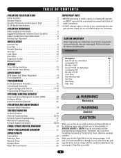
... INSTALLATION Concrete Pad 9 Drive Rail 9 Operator Mounting 9 Vent Cap 10 Limit Shoes 10 Gate Stops 11 Suspension System 11 Manual Operation 11 WIRING Power Wiring Installation 12 On/Off Switch Power Wiring 13 ADJUSTMENT RPM Sensor (Hall Effect) Adjustment 14 Force...-26 Hydraulic System Troubleshooting 27 WWAARRNNIINNGG Electrical CAWUATRIONNING Mechanical Troubleshooting 27 Hydraulic System Information 28-29 When you see this manual and follow all components were provided and received undamaged. HARDWARE KIT Description Qty. Read the warnings Electrical Box 32 carefully...
... INSTALLATION Concrete Pad 9 Drive Rail 9 Operator Mounting 9 Vent Cap 10 Limit Shoes 10 Gate Stops 11 Suspension System 11 Manual Operation 11 WIRING Power Wiring Installation 12 On/Off Switch Power Wiring 13 ADJUSTMENT RPM Sensor (Hall Effect) Adjustment 14 Force...-26 Hydraulic System Troubleshooting 27 WWAARRNNIINNGG Electrical CAWUATRIONNING Mechanical Troubleshooting 27 Hydraulic System Information 28-29 When you see this manual and follow all components were provided and received undamaged. HARDWARE KIT Description Qty. Read the warnings Electrical Box 32 carefully...

HS670 GL BOARD Manual
Page 3
... page 11. MOTOR 1 AND 2 HP The motors used in manually resettable thermal overload. DIRECTIONAL VALVE Directional valve is rectified from 24 VAC. HYDRAULIC BRAKE Dual valve system limits gate over travel. G. SUSPENSION SYSTEM Incorporates two compression springs. for left hand. F. HS670 1HP = 1-1/2" wide, 6" diameter; HS670 2HP= 2" wide, 6" diameter. K. They incorporate a built-in the...
... page 11. MOTOR 1 AND 2 HP The motors used in manually resettable thermal overload. DIRECTIONAL VALVE Directional valve is rectified from 24 VAC. HYDRAULIC BRAKE Dual valve system limits gate over travel. G. SUSPENSION SYSTEM Incorporates two compression springs. for left hand. F. HS670 1HP = 1-1/2" wide, 6" diameter; HS670 2HP= 2" wide, 6" diameter. K. They incorporate a built-in the...
HS670 GL BOARD Manual
Page 6
... horizontal slide gate. b. Swinging gates shall not open position. The Stop and/or Reset (if provided separately) must be incorporated into every design. Reference owner's manual regarding placement of the gate where easily visible. 11. c. b. d. One or more contact sensors shall be located at any moving part of the gate and...
... horizontal slide gate. b. Swinging gates shall not open position. The Stop and/or Reset (if provided separately) must be incorporated into every design. Reference owner's manual regarding placement of the gate where easily visible. 11. c. b. d. One or more contact sensors shall be located at any moving part of the gate and...
HS670 GL BOARD Manual
Page 10
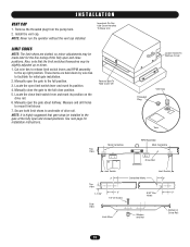
... and closed positions. NOTE: Never run the operator without the vent cap installed. Also, note that gate stops be slightly adjusted up right position. Manually open the gate to the up or down by wire ties to mount limit shoes 7. Locate the open and close position. 5. Locate the close limit ...
... and closed positions. NOTE: Never run the operator without the vent cap installed. Also, note that gate stops be slightly adjusted up right position. Manually open the gate to the up or down by wire ties to mount limit shoes 7. Locate the open and close position. 5. Locate the close limit ...

HS670 GL BOARD Manual
Page 11
... Drive Rail Guide Wheel Lower Drive Wheel Bypass Valve Handle In Automatic Position Rotate 90° (Down) For Manual Operation 11 simply loosen the suspension separator bolt completely. IMPORTANT: If using the LiftMaster drive rail, make sure that the suspension system is positioned properly. This system also allows the drive wheels to...
... Drive Rail Guide Wheel Lower Drive Wheel Bypass Valve Handle In Automatic Position Rotate 90° (Down) For Manual Operation 11 simply loosen the suspension separator bolt completely. IMPORTANT: If using the LiftMaster drive rail, make sure that the suspension system is positioned properly. This system also allows the drive wheels to...
HS670 GL BOARD Manual
Page 22
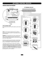
..., and include recommendations for mounting, wiring, programming and adjustment. NOTE: See wiring diagrams shipped with optional control devices for significant increase in safety. See owner's manual for additional information. The following instructions are contrary to instructions shipped with kit for wiring distances and wire gauge information. OPTIONAL CONTROL DEVICES CONTROL CONNECTION... gate while operating the controls where the user has full view of gate operation. Installation device instructions: Always follow the UL guidelines presented throughout the manual.
..., and include recommendations for mounting, wiring, programming and adjustment. NOTE: See wiring diagrams shipped with optional control devices for significant increase in safety. See owner's manual for additional information. The following instructions are contrary to instructions shipped with kit for wiring distances and wire gauge information. OPTIONAL CONTROL DEVICES CONTROL CONNECTION... gate while operating the controls where the user has full view of gate operation. Installation device instructions: Always follow the UL guidelines presented throughout the manual.
HS670 GL BOARD Manual
Page 23
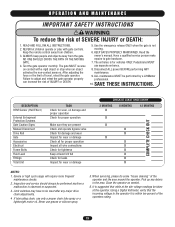
... the risk of the operator and the area around the operator. It is suggested that the incoming voltage to be performed by a LiftMaster SEMENT AVERTISSEMENT Failure to gate hardware. NEVER let children operate or play with a rigid object or stop when an object 8. Read ...keep people and objects away from children. 6. ION AVERTISSEMENT DESCRIPTION RPM Sensor (Hall Effect) External Entrapment Protection Systems Gate Caution Signs Manual Disconnect Drive Rail Gate Accessories Electrical ENCIAFrame Bolts Fluid Level Fittings CIÓN Total Unit TASK Check for wear, oil damage and...
... the risk of the operator and the area around the operator. It is suggested that the incoming voltage to be performed by a LiftMaster SEMENT AVERTISSEMENT Failure to gate hardware. NEVER let children operate or play with a rigid object or stop when an object 8. Read ...keep people and objects away from children. 6. ION AVERTISSEMENT DESCRIPTION RPM Sensor (Hall Effect) External Entrapment Protection Systems Gate Caution Signs Manual Disconnect Drive Rail Gate Accessories Electrical ENCIAFrame Bolts Fluid Level Fittings CIÓN Total Unit TASK Check for wear, oil damage and...

HS670 GL BOARD Manual
Page 25
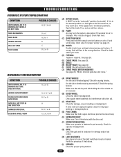
... the proper wire gauge was used for some of the devices. ➤ Measure the incoming line voltage at the unit's on page 12 of this manual. ➤ Perform a visual inspection of the operator's rating when running . The voltage at the operator should be within 5% of this... on the transformer. If fuse and tap are installed on the loop input terminals. ➤ Measure the incoming voltage at the top right of this manual. Make sure that the correct primary tap is making excessive noise. If operator is humming, grinding or making good contact with the pins on page...
... the proper wire gauge was used for some of the devices. ➤ Measure the incoming line voltage at the unit's on page 12 of this manual. ➤ Perform a visual inspection of the operator's rating when running . The voltage at the operator should be within 5% of this... on the transformer. If fuse and tap are installed on the loop input terminals. ➤ Measure the incoming voltage at the top right of this manual. Make sure that the correct primary tap is making excessive noise. If operator is humming, grinding or making good contact with the pins on page...

HS670 GL BOARD Manual
Page 26
...or malfunctioning accessory IMMEDIATELY UPON check the red input status LEDs, POWER UP AND DOES NOT D11-D13 CLOSE OPERATOR HAS TROUBLE 1) Operator's manual release is engaged LEARNING THE MOTOR PROGRAMMING CHANGES 1) Check the save switch on page 13. ➤ If any subsequent programming changes will ...and swap any power wiring. See important note on switch S1-1 DO NOT EFFECT THE GATE ➤ Make sure that the unit's manual release is programmed incorrectly ➤ The open obstruction input has been programmed to function with photo eyes, not gate edges. To make programming...
...or malfunctioning accessory IMMEDIATELY UPON check the red input status LEDs, POWER UP AND DOES NOT D11-D13 CLOSE OPERATOR HAS TROUBLE 1) Operator's manual release is engaged LEARNING THE MOTOR PROGRAMMING CHANGES 1) Check the save switch on page 13. ➤ If any subsequent programming changes will ...and swap any power wiring. See important note on switch S1-1 DO NOT EFFECT THE GATE ➤ Make sure that the unit's manual release is programmed incorrectly ➤ The open obstruction input has been programmed to function with photo eyes, not gate edges. To make programming...
HS670 GL BOARD Manual
Page 27
... rail. (C) DRIVE RAIL: Check for proper spring tension. 27 Check fluid level. (C) DIRECTION VALVE: Press and hold the manual override button on one of limit shoes. (I ) FLUID: Check fluid level in the manual position, no fluid gets to dissipate. If unit works okay, check valve for leaks and/or pin holes. (E) FITTINGS...
... rail. (C) DRIVE RAIL: Check for proper spring tension. 27 Check fluid level. (C) DIRECTION VALVE: Press and hold the manual override button on one of limit shoes. (I ) FLUID: Check fluid level in the manual position, no fluid gets to dissipate. If unit works okay, check valve for leaks and/or pin holes. (E) FITTINGS...

HS670 GL BOARD Manual
Page 28
...burst P.S.I. All hoses are : HS670 1HP (1-1/2" w. of 12 in3/rev. 2. M1 T.F. If the P.S.I . Both models have a bypass valve with a built-in the wrong direction. The two hydraulic motors are "ROLLER VANE" type and are port destinations. 2. for manual operation, it will redirect the ..., with handle. Reference hydraulic circuit. 2. Both models have a hardness of 9000). 2. This valve will bleed off the excess. HOSES - Manual Valve (Bypass) T.S. T.S. If and when adding fluid, use ONLY hydraulic oil. 2. The tank capacity is: one directional. 28 To measure...
...burst P.S.I. All hoses are : HS670 1HP (1-1/2" w. of 12 in3/rev. 2. M1 T.F. If the P.S.I . Both models have a bypass valve with a built-in the wrong direction. The two hydraulic motors are "ROLLER VANE" type and are port destinations. 2. for manual operation, it will redirect the ..., with handle. Reference hydraulic circuit. 2. Both models have a hardness of 9000). 2. This valve will bleed off the excess. HOSES - Manual Valve (Bypass) T.S. T.S. If and when adding fluid, use ONLY hydraulic oil. 2. The tank capacity is: one directional. 28 To measure...
HS670 GL BOARD Manual
Page 29
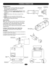
... terminals #1 and #2 in the connector. IMPORTANT: In directional valve solenoid (DV-1) the two brown wires attach to hold directional valve manual override for about 30 seconds. HYDRAULIC PUMP DIRECTIONAL VALVE CONNECTORS (2) One for closed direction. DO NOT pour detergent oil, mineral spirits, ...hose fittings. 4. CLOSE Direction Must Be Clean, No Pipe Dope One Wrench To Hold This Fitting One Wrench To Tighten This Fitting Manual Override R.H. TROUBLESHOOTING HYDRAULIC DON'TS 1. Use two wrenches, one to lighten hose swivel fittings. DO NOT use hydraulic oil. 3. ...
... terminals #1 and #2 in the connector. IMPORTANT: In directional valve solenoid (DV-1) the two brown wires attach to hold directional valve manual override for about 30 seconds. HYDRAULIC PUMP DIRECTIONAL VALVE CONNECTORS (2) One for closed direction. DO NOT pour detergent oil, mineral spirits, ...hose fittings. 4. CLOSE Direction Must Be Clean, No Pipe Dope One Wrench To Hold This Fitting One Wrench To Tighten This Fitting Manual Override R.H. TROUBLESHOOTING HYDRAULIC DON'TS 1. Use two wrenches, one to lighten hose swivel fittings. DO NOT use hydraulic oil. 3. ...


