GT- Logic 4 Installation Manual
Page 1
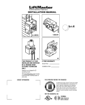
... incorporates a self-diagnostic feature built into the (MAS) Maintenance Alert System LED. INSTALLATION MANUAL H, J, AND HJ T AND APT L 4 ogic L3 GH THIS PRODUCT IS TO BE INSTALLED AND SERVICED BY A TRAINED DOOR SYSTEMS TECHNICIAN ONLY. Visit www.liftmaster.com to set number of cycles/months is reached or when the operator requires...
... incorporates a self-diagnostic feature built into the (MAS) Maintenance Alert System LED. INSTALLATION MANUAL H, J, AND HJ T AND APT L 4 ogic L3 GH THIS PRODUCT IS TO BE INSTALLED AND SERVICED BY A TRAINED DOOR SYSTEMS TECHNICIAN ONLY. Visit www.liftmaster.com to set number of cycles/months is reached or when the operator requires...

GT- Logic 4 Installation Manual
Page 2
... TYPICAL INSTALLATION 16-17 Determine Mounting Location 16 Mounting 17 Install the Manual Disconnect 17 WIRING 18-19 Power and Ground 18 Control Station 19 ENTRAPMENT PROTECTION 20-22 LiftMaster Monitored Entrapment Protection (LMEP 20 Install the Photoelectric Sensors (Provided 21 ...Mount the Photoelectric Sensors (Provided 22 Wire the LiftMaster Monitored Entrapment Protection (LMEP) Devices 22 ADJUSTMENT 23-24 Limit Adjustment 23 Clutch Adjustment (Belt Drive Model Operators 24 TESTING 25 MANUAL RELEASE 26-27 Emergency Disconnect System Model GT and T...
... TYPICAL INSTALLATION 16-17 Determine Mounting Location 16 Mounting 17 Install the Manual Disconnect 17 WIRING 18-19 Power and Ground 18 Control Station 19 ENTRAPMENT PROTECTION 20-22 LiftMaster Monitored Entrapment Protection (LMEP 20 Install the Photoelectric Sensors (Provided 21 ...Mount the Photoelectric Sensors (Provided 22 Wire the LiftMaster Monitored Entrapment Protection (LMEP) Devices 22 ADJUSTMENT 23-24 Limit Adjustment 23 Clutch Adjustment (Belt Drive Model Operators 24 TESTING 25 MANUAL RELEASE 26-27 Emergency Disconnect System Model GT and T...
GT- Logic 4 Installation Manual
Page 3
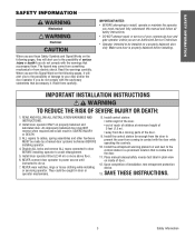
... door is visible from electric shock. NEVER connect door operator to power source until instructed to avoid entanglement. 5. When you see this manual and follow all safety instructions. WARNING When you see these Safety Symbols and Signal Words on the following pages, it . Install door operator... on wall next to cables, spring assemblies and other hardware MUST be installed on a properly balanced door WARNING WARNING only. Place manual release/safety reverse test label in a prominent location that accompany it will alert you to your commercial door and WARNING gate operator ...
... door is visible from electric shock. NEVER connect door operator to power source until instructed to avoid entanglement. 5. When you see this manual and follow all safety instructions. WARNING When you see these Safety Symbols and Signal Words on the following pages, it . Install door operator... on wall next to cables, spring assemblies and other hardware MUST be installed on a properly balanced door WARNING WARNING only. Place manual release/safety reverse test label in a prominent location that accompany it will alert you to your commercial door and WARNING gate operator ...

GT- Logic 4 Installation Manual
Page 4
...to OPEN & STOP, constant pressure to CLOSE, plus wiring for 3/4 HP and higher (all components were provided. See page 29 for emergency manual door operation. Carton inventory/Operator specifications - LIMIT ADJUST Linear driven, fully adjustable screw type cams. Adjustable to provide non-contact safety ...all GT models) Entrapment Protection Device: Model CPS-U photoelectric sensors (standard) NOTE: The tracks are shipped separately. ENTRAPMENT PROTECTION: LiftMaster Monitored Entrapment Protection (LMEP) Photoelectric Sensors (CPS-U Through beam used to 24 feet.
...to OPEN & STOP, constant pressure to CLOSE, plus wiring for 3/4 HP and higher (all components were provided. See page 29 for emergency manual door operation. Carton inventory/Operator specifications - LIMIT ADJUST Linear driven, fully adjustable screw type cams. Adjustable to provide non-contact safety ...all GT models) Entrapment Protection Device: Model CPS-U photoelectric sensors (standard) NOTE: The tracks are shipped separately. ENTRAPMENT PROTECTION: LiftMaster Monitored Entrapment Protection (LMEP) Photoelectric Sensors (CPS-U Through beam used to 24 feet.

GT- Logic 4 Installation Manual
Page 13
... reverse and auxiliary devices to provide non-contact safety protection. SAFETY DISCONNECT: Model J . . . . .Floor level disconnect for manual door operation Model H and GH Floor level chain hoist with electrical interlock for optional wiring types and operating modes. LIMIT ADJUST Linear... check that all components were provided. Hoist and Jackshaft See page 29 for manual door operation Model HJ Includes both floor level disconnect systems stated above ENTRAPMENT PROTECTION: LiftMaster Monitored Entrapment Protection (LMEP) Photoelectric Sensors (CPS-U Through beam used to open...
... reverse and auxiliary devices to provide non-contact safety protection. SAFETY DISCONNECT: Model J . . . . .Floor level disconnect for manual door operation Model H and GH Floor level chain hoist with electrical interlock for optional wiring types and operating modes. LIMIT ADJUST Linear... check that all components were provided. Hoist and Jackshaft See page 29 for manual door operation Model HJ Includes both floor level disconnect systems stated above ENTRAPMENT PROTECTION: LiftMaster Monitored Entrapment Protection (LMEP) Photoelectric Sensors (CPS-U Through beam used to open...

GT- Logic 4 Installation Manual
Page 16
... or adjust doors, door springs, cable, pulleys, brackets or their hardware, ALL of which are under EXTREME tension and can be fastened securely and with manual hand chain systems, the handing of the operator must : a. This surface must be switched.
... or adjust doors, door springs, cable, pulleys, brackets or their hardware, ALL of which are under EXTREME tension and can be fastened securely and with manual hand chain systems, the handing of the operator must : a. This surface must be switched.

GT- Logic 4 Installation Manual
Page 17
.... 3 Wrap the drive chain around the door sprocket and the drive sprocket then secure with the set screws in place. 1 4 3 2 HOIST AND JACKSHAFT INSTALL THE MANUAL DISCONNECT 1 Fasten Door retaining bracket 4 feet above the floor. 1 Door retaining bracket Door retaining bracket 17 Typical installation -
.... 3 Wrap the drive chain around the door sprocket and the drive sprocket then secure with the set screws in place. 1 4 3 2 HOIST AND JACKSHAFT INSTALL THE MANUAL DISCONNECT 1 Fasten Door retaining bracket 4 feet above the floor. 1 Door retaining bracket Door retaining bracket 17 Typical installation -
GT- Logic 4 Installation Manual
Page 23
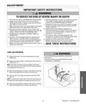
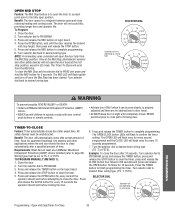
...23 Adjustment - NO ONE SHOULD CROSS THE PATH OF THE MOVING DOOR. 5. Entrapment Protection device MUST be tested. See door manufacturer's owners manual. 11. WARNING WARNING LIMIT ADJUSTMENT CAUTION 1 Begin with the notches of which are under EXTREME tension, MUST be seen clearly, it is properly...the switches are no obstructions to the CLOSE limits (2). Limits Adjustment READ AND FOLLOW ALL WARNINGS AND INSTRUCTIONS. 2. If possible, use manual release handle unless doorway is fully seated with the door in sight until completely closed position to set the OPEN limit (3). After ...
...23 Adjustment - NO ONE SHOULD CROSS THE PATH OF THE MOVING DOOR. 5. Entrapment Protection device MUST be tested. See door manufacturer's owners manual. 11. WARNING WARNING LIMIT ADJUSTMENT CAUTION 1 Begin with the notches of which are under EXTREME tension, MUST be seen clearly, it is properly...the switches are no obstructions to the CLOSE limits (2). Limits Adjustment READ AND FOLLOW ALL WARNINGS AND INSTRUCTIONS. 2. If possible, use manual release handle unless doorway is fully seated with the door in sight until completely closed position to set the OPEN limit (3). After ...
GT- Logic 4 Installation Manual
Page 25
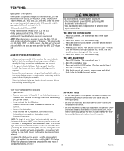
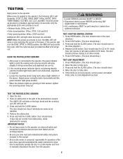
... (The door should close button. Press STOP button. (The door should continue closing after 5 seconds and will not provide AVERTISSEMENT this manual. • Be sure the owner or person(s) responsible for operation of the photoelectric sensors. Press OPEN button. (The door should move... close . 5. If door did not reverse from the operator. 25 Testing IMPORTANT NOTES: ADVERTENCIA • Do not leave power to manually disconnect the door from obstruction, check photoelectric sensors. If the green indicator lights are glowing in the open direction.) 2. Door will be...
... (The door should close button. Press STOP button. (The door should continue closing after 5 seconds and will not provide AVERTISSEMENT this manual. • Be sure the owner or person(s) responsible for operation of the photoelectric sensors. Press OPEN button. (The door should move... close . 5. If door did not reverse from the operator. 25 Testing IMPORTANT NOTES: ADVERTENCIA • Do not leave power to manually disconnect the door from obstruction, check photoelectric sensors. If the green indicator lights are glowing in the open direction.) 2. Door will be...
GT- Logic 4 Installation Manual
Page 26
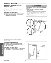
... handle unless doorway is CLOSED. TO RECONNECT DOOR ARM TO TROLLEY 2 Lift free end of persons and obstructions. 1 AVERTISSEMENT ATTENTION 2 NOTICE MANUAL RELEASE EMERGENCY DISCONNECT SYSTEM MODEL APT TO DISCONNECT DOOR FROM OPERATOR The door should be in an open . TO RECONNECT DOOR ARM TO TROLLEY ...The trolley will open door falling rapidly and/or unexpectedly. • NEVER use emergency release handle to engage roll pin. Manual Release 26 ADVERTENCIA PRECAUCIÓN 1 N O T I C E Emergency disconnect will reconnect on the emergency release handle and raise or lower the door...
... handle unless doorway is CLOSED. TO RECONNECT DOOR ARM TO TROLLEY 2 Lift free end of persons and obstructions. 1 AVERTISSEMENT ATTENTION 2 NOTICE MANUAL RELEASE EMERGENCY DISCONNECT SYSTEM MODEL APT TO DISCONNECT DOOR FROM OPERATOR The door should be in an open . TO RECONNECT DOOR ARM TO TROLLEY ...The trolley will open door falling rapidly and/or unexpectedly. • NEVER use emergency release handle to engage roll pin. Manual Release 26 ADVERTENCIA PRECAUCIÓN 1 N O T I C E Emergency disconnect will reconnect on the emergency release handle and raise or lower the door...
GT- Logic 4 Installation Manual
Page 27
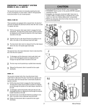
...keyhole of emergency or power failure. The disconnect chain may now be released from the door operator and a disconnect chain with a manual hoist. HJ 4 27 3 4 2 1 Manual Release Refer to operate the door again electrically. CAUTION To prevent possible SERIOUS INJURY from a moving chain: • DISCONNECT electric...on one side or the other of the continuous loop hoist chain. 4 Release the disconnect chain to the appropriate instructions below for manually operating the door in case of the chain keeper mounted on the wall. 2 To disengage, pull the disconnect chain and secure ...
...keyhole of emergency or power failure. The disconnect chain may now be released from the door operator and a disconnect chain with a manual hoist. HJ 4 27 3 4 2 1 Manual Release Refer to operate the door again electrically. CAUTION To prevent possible SERIOUS INJURY from a moving chain: • DISCONNECT electric...on one side or the other of the continuous loop hoist chain. 4 Release the disconnect chain to the appropriate instructions below for manually operating the door in case of the chain keeper mounted on the wall. 2 To disengage, pull the disconnect chain and secure ...
GT- Logic 4 Installation Manual
Page 33
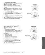
...on wiring type T E2 D1 C2 B2 TS FSTS DIAG OPTN PROG WARNING To prevent possible SEVERE INJURY or DEATH: CAUTION • Install a LiftMaster Monitored Entrapment Protection (LMEP) device. • Activate door ONLY when it can be unobstructed. Press and release the MID button to clear the...the selector dial to TS, T or FSTS. Example: To close seconds programmed. PROGRAM, press and release the TIMER button, press and TO PROGRAM MANUALLY (METHOD 1): release the STOP button to PROGRAM. Turn the selector dial to clear the timer, press and release the 1. Press the TIMER 3. ...
...on wiring type T E2 D1 C2 B2 TS FSTS DIAG OPTN PROG WARNING To prevent possible SEVERE INJURY or DEATH: CAUTION • Install a LiftMaster Monitored Entrapment Protection (LMEP) device. • Activate door ONLY when it can be unobstructed. Press and release the MID button to clear the...the selector dial to TS, T or FSTS. Example: To close seconds programmed. PROGRAM, press and release the TIMER button, press and TO PROGRAM MANUALLY (METHOD 1): release the STOP button to PROGRAM. Turn the selector dial to clear the timer, press and release the 1. Press the TIMER 3. ...
GT- Logic 4 Installation Manual
Page 35
...The operator can learn the time it will stop, limiting damage to the door and operator. In the event the application requires the MRT be manually learned for the door to 90 seconds e. Start with the door in the closed position. 2. NOTE: To reset MRT only, turn selector ... Program: NOTE: The default setting for 5 seconds. SELECTOR DIAL T E2 D1 C2 B2 TS FSTS DIAG OPTN PROG Operation will be learned g. The LiftMaster Monitored Entrapment Protection (LMEP) device will vary depending on wiring type T E2 D1 C2 B2 TS FSTS DIAG OPTN PROG RESETTING FACTORY DEFAULTS CLEARING MEMORY...
...The operator can learn the time it will stop, limiting damage to the door and operator. In the event the application requires the MRT be manually learned for the door to 90 seconds e. Start with the door in the closed position. 2. NOTE: To reset MRT only, turn selector ... Program: NOTE: The default setting for 5 seconds. SELECTOR DIAL T E2 D1 C2 B2 TS FSTS DIAG OPTN PROG Operation will be learned g. The LiftMaster Monitored Entrapment Protection (LMEP) device will vary depending on wiring type T E2 D1 C2 B2 TS FSTS DIAG OPTN PROG RESETTING FACTORY DEFAULTS CLEARING MEMORY...

GT- Logic 4 Installation Manual
Page 36
ASpVrocEketRs TISSEMENLCuhTbercikcasteet. BeAlt TTENTION Check condition and tension. Manual Disconnect Check and operate. Motor bearings are available. OPEN for every 5,000 cycles and CLOSE for excessive slack. Check alignment and functionality....Press and release the MRT button on the logic board. 4. Start with the door in service. Check and adjust as required. Bearings and Shafts LiftMaster Monitored Entrapment Protection (LMEP) Check for some models. z Inspect and service whenever a malfunction is adjusted at the intervals listed in the following chart:...
ASpVrocEketRs TISSEMENLCuhTbercikcasteet. BeAlt TTENTION Check condition and tension. Manual Disconnect Check and operate. Motor bearings are available. OPEN for every 5,000 cycles and CLOSE for excessive slack. Check alignment and functionality....Press and release the MRT button on the logic board. 4. Start with the door in service. Check and adjust as required. Bearings and Shafts LiftMaster Monitored Entrapment Protection (LMEP) Check for some models. z Inspect and service whenever a malfunction is adjusted at the intervals listed in the following chart:...

GT- Logic 4 Installation Manual
Page 38
... wiring connections or a faulty control transformer b) Hoist interlock switch ➤ Repair or replace connections or control transformer. ➤ Check interlock. Verify the manual release chain is running. correctly b) Interlock switch ➤ Check interlock switch(es) for 5 seconds. AFTER STOPPING, ONLY CONSTANT PRESSURE COMMANDS WILL MOVE ...A or B LED should turn on . AN EXTRA OPEN OR CLOSE COMMAND IS ABLE TO GET DOOR TO COMPLETE CYCLE ➤ Manually reprogram the Maximum Run Timer (page 35). AN EXTRA OPEN IS ABLE TO GET THE DOOR TO OPEN COMPLETELY There may need to...
... wiring connections or a faulty control transformer b) Hoist interlock switch ➤ Repair or replace connections or control transformer. ➤ Check interlock. Verify the manual release chain is running. correctly b) Interlock switch ➤ Check interlock switch(es) for 5 seconds. AFTER STOPPING, ONLY CONSTANT PRESSURE COMMANDS WILL MOVE ...A or B LED should turn on . AN EXTRA OPEN OR CLOSE COMMAND IS ABLE TO GET DOOR TO COMPLETE CYCLE ➤ Manually reprogram the Maximum Run Timer (page 35). AN EXTRA OPEN IS ABLE TO GET THE DOOR TO OPEN COMPLETELY There may need to...

GT- Logic 4 Installation Manual
Page 39
.... Error codes will resume. TROUBLESHOOTING ERROR CODES Logic 4.0 operators incorporate a self diagnostic feature built into option card receptacles LiftMaster Monitored Entrapment Protection (LMEP) device faulted or removed for any faults (i.e., Bad Limit switch), manually learn Max Run Timer (page 35) OR reset factory defaults (page 35). Check AC line for low voltage...
.... Error codes will resume. TROUBLESHOOTING ERROR CODES Logic 4.0 operators incorporate a self diagnostic feature built into option card receptacles LiftMaster Monitored Entrapment Protection (LMEP) device faulted or removed for any faults (i.e., Bad Limit switch), manually learn Max Run Timer (page 35) OR reset factory defaults (page 35). Check AC line for low voltage...
GT- Logic 4 User Manual
Page 5
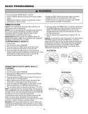
... be activated by the Single Button Control (terminal 1) only. AVERTISSEMENT PROGRAM, press and release the TIMER button, press and AVE TO PROGRAM MANUALLY (METHOD 1): release the STOP button to TS, T or FSTS. CLOSE button four times for 10 seconds. the OPEN button 10 times...sight until OPEN and OLS flashes then release. BASIC PROGRAMMING WARNING W To prevent possible SEVERE INJURY or DEATH: CAUTION • Install a LiftMaster Monitored Entrapment Protection (LMEP) • Activate door ONLY when it can be reactivated on the logic board. adjusted and there are no obstructions...
... be activated by the Single Button Control (terminal 1) only. AVERTISSEMENT PROGRAM, press and release the TIMER button, press and AVE TO PROGRAM MANUALLY (METHOD 1): release the STOP button to TS, T or FSTS. CLOSE button four times for 10 seconds. the OPEN button 10 times...sight until OPEN and OLS flashes then release. BASIC PROGRAMMING WARNING W To prevent possible SEVERE INJURY or DEATH: CAUTION • Install a LiftMaster Monitored Entrapment Protection (LMEP) • Activate door ONLY when it can be reactivated on the logic board. adjusted and there are no obstructions...
GT- Logic 4 User Manual
Page 6
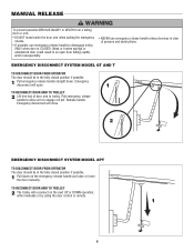
... If possible, use emergency release handle unless doorway is CLOSED. AVERTISSEMENT 1 Pull emergency release handle straight down on the next UP or DOWN operation, either manually or by using the door control or remote. 1 N O T I C E 6 AD A Emergency disconnect will open door falling rapidly and/or ...211;N TO RECONNECT DOOR ARM TO TROLLEY 2 The trolley will reconnect on the emergency release handle and raise or lower the door manually. Release handle. of door arm to trolley. Emergency disconnect will close. AVE AV 2 NOTICE EMERGENCY DISCONNECT SYSTEM MODEL APT TO ...
... If possible, use emergency release handle unless doorway is CLOSED. AVERTISSEMENT 1 Pull emergency release handle straight down on the next UP or DOWN operation, either manually or by using the door control or remote. 1 N O T I C E 6 AD A Emergency disconnect will open door falling rapidly and/or ...211;N TO RECONNECT DOOR ARM TO TROLLEY 2 The trolley will reconnect on the emergency release handle and raise or lower the door manually. Release handle. of door arm to trolley. Emergency disconnect will close. AVE AV 2 NOTICE EMERGENCY DISCONNECT SYSTEM MODEL APT TO ...
GT- Logic 4 User Manual
Page 7
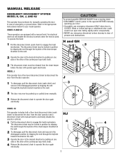
... ADVERTENCIA MODEL HJ This operator includes both a floor level disconnect chain (sash chain) to the operator BEFORE manually operating your model operator. Weak or broken springs or unbalanced door could result in the disengaged position by slipping the... the door again electrically. H and GH 3 AVERTISSEMENT ATTENTION 2 1 J 3 1 2 3 Release the disconnect chain to engage the hoist mechanism. MANUAL RELEASE WARNING EMERGENCY DISCONNECT SYSTEM MODEL H, GH, J, AND HJ This operator has provisions for your door. • If possible, use emergency disconnect unless...
... ADVERTENCIA MODEL HJ This operator includes both a floor level disconnect chain (sash chain) to the operator BEFORE manually operating your model operator. Weak or broken springs or unbalanced door could result in the disengaged position by slipping the... the door again electrically. H and GH 3 AVERTISSEMENT ATTENTION 2 1 J 3 1 2 3 Release the disconnect chain to engage the hoist mechanism. MANUAL RELEASE WARNING EMERGENCY DISCONNECT SYSTEM MODEL H, GH, J, AND HJ This operator has provisions for your door. • If possible, use emergency disconnect unless...
GT- Logic 4 User Manual
Page 8
... to the operator on the logic board and the receiving eye LED will go out. Once the power up process is applied to manually disconnect the door from obstruction, check photoelectric sensors. After the code has been provided the MAS LED will turn off. 3. WARNING...Fully closed position: 24Vac, STOP, CLS and SLS • Fully opened position: 24Vac, STOP and OLS Additional LED's will not provide AVERTISSEMENT this manual. • Be sure the owner or person(s) responsible for operation of the photoelectric sensors. Open the door. TEST THE PHOTOELECTRIC SENSORS 1. The ...
... to the operator on the logic board and the receiving eye LED will go out. Once the power up process is applied to manually disconnect the door from obstruction, check photoelectric sensors. After the code has been provided the MAS LED will turn off. 3. WARNING...Fully closed position: 24Vac, STOP, CLS and SLS • Fully opened position: 24Vac, STOP and OLS Additional LED's will not provide AVERTISSEMENT this manual. • Be sure the owner or person(s) responsible for operation of the photoelectric sensors. Open the door. TEST THE PHOTOELECTRIC SENSORS 1. The ...


