Dial Code LC and VF Series Manual
Page 1
I LT- DIAL CODE SERIES OWNER S MANUAL Telephone entry systems with two line large LC or VF displays with B U I N surge suppression VISIT US ON THE WEB www.chamberlain.com
I LT- DIAL CODE SERIES OWNER S MANUAL Telephone entry systems with two line large LC or VF displays with B U I N surge suppression VISIT US ON THE WEB www.chamberlain.com
Dial Code LC and VF Series Manual
Page 2
... Viewing Software Version 20 Warning and Precautions 21 Programming the Processor 22 Selecting Program Mode 23 Resident Information 24 Transmitter / Card Programming 25 Area Codes 26 Utility Codes 27 Password 28 Clock / Timer 29-31 Strike Time 32 Talk Time 32 Greeting 33 Volume Adjustment 33 Back-Up Memory 34 Error Messages...
... Viewing Software Version 20 Warning and Precautions 21 Programming the Processor 22 Selecting Program Mode 23 Resident Information 24 Transmitter / Card Programming 25 Area Codes 26 Utility Codes 27 Password 28 Clock / Timer 29-31 Strike Time 32 Talk Time 32 Greeting 33 Volume Adjustment 33 Back-Up Memory 34 Error Messages...
Dial Code LC and VF Series Manual
Page 3
...- Immune to avoid unpleasant cutoff between visitor and resident. • Both DTMF tone and rotary dial detection. • Programmable via modem (optional). • FCC part 68 ,15 & Canadian... to record 5 seconds per system. - Relative Humidity: 5% - 95% non-condensing. • Dimensions: 11 1/4" W X 16 7/16" H X 4 1/8" D • Shipping Weight: Approximately 25 lbs. Battery enables dial out, program, & display. - Non-Volatile removable SRAM memory has unlimited write cycles (unlike EEPROM). - ENTER RASE EX T Q P OGR M E W S R D A X SHIFT Z SP CE BAR 3 2...
...- Immune to avoid unpleasant cutoff between visitor and resident. • Both DTMF tone and rotary dial detection. • Programmable via modem (optional). • FCC part 68 ,15 & Canadian... to record 5 seconds per system. - Relative Humidity: 5% - 95% non-condensing. • Dimensions: 11 1/4" W X 16 7/16" H X 4 1/8" D • Shipping Weight: Approximately 25 lbs. Battery enables dial out, program, & display. - Non-Volatile removable SRAM memory has unlimited write cycles (unlike EEPROM). - ENTER RASE EX T Q P OGR M E W S R D A X SHIFT Z SP CE BAR 3 2...
Dial Code LC and VF Series Manual
Page 4
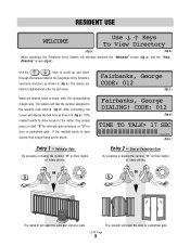
When the desired name is found, enter the corresponding 3-digit code. Vehicular Gate By pressing or dialing the number "9" on their digital or rotary phone, Fairbanks, George CODE: 012 (fig c.) Fairbanks, George DIALING! The resident will display the talk time as shown in (fig c.) The names are ... System's electronic directory as shown in alphabetical order by last name. The system will dial the number assigned to the resident code entered. (fig d.) After connecting, the screen will open the vehicular entrance gate. CODE: 012 (fig d.) TIME TO TALK> 17 SEC ___ (fig e.) Entry 2 ...
When the desired name is found, enter the corresponding 3-digit code. Vehicular Gate By pressing or dialing the number "9" on their digital or rotary phone, Fairbanks, George CODE: 012 (fig c.) Fairbanks, George DIALING! The resident will display the talk time as shown in (fig c.) The names are ... System's electronic directory as shown in alphabetical order by last name. The system will dial the number assigned to the resident code entered. (fig d.) After connecting, the screen will open the vehicular entrance gate. CODE: 012 (fig d.) TIME TO TALK> 17 SEC ___ (fig e.) Entry 2 ...
Dial Code LC and VF Series Manual
Page 5
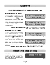
.... * INVALID ENTRY * Invalid 6-Digit Code (fig b.) EXAMPLE - RESIDENT USE USING KEYCODES AND UTILITY CODES (ACTIVE ENTRY 1 ONLY) RESIDENT 6-DIGIT KEYCODES Residents are equipped with 60 different Utility codes. UTILITY CODE 8716 = 8 71 6 SCREEN SAVER MODE (VF ONLY) If the VF Dial Code System is inactive for entry, the *... seconds it is not within the time zone set, the Utility Company must first push the key once and enter their 4-digit code. If an incorrect keycode is not available while in program mode. If, however, it is within the programmed time * ACCESS GRANTED...
.... * INVALID ENTRY * Invalid 6-Digit Code (fig b.) EXAMPLE - RESIDENT USE USING KEYCODES AND UTILITY CODES (ACTIVE ENTRY 1 ONLY) RESIDENT 6-DIGIT KEYCODES Residents are equipped with 60 different Utility codes. UTILITY CODE 8716 = 8 71 6 SCREEN SAVER MODE (VF ONLY) If the VF Dial Code System is inactive for entry, the *... seconds it is not within the time zone set, the Utility Company must first push the key once and enter their 4-digit code. If an incorrect keycode is not available while in program mode. If, however, it is within the programmed time * ACCESS GRANTED...
Dial Code LC and VF Series Manual
Page 6
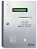
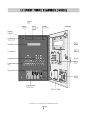
LC/VF Page 5 LC ENTRY PHONE FEATURES (INSIDE) Mounting Holes (4) Processor Key Release / Lock LC Display Processor Unit Dialing Keys Programming Keys Parallel Port Memory Card Memory Card Slot Memory Card Release Buttons Processor Power Switch Microphone POWER GATE RELAY DOOR RELAY Surge Suppressor Terminal Board Postal Lock Setup Display Window Stainless Steel Door Key Lock External Keypad External Speaker All components and specifications are subject to change without notice.
LC/VF Page 5 LC ENTRY PHONE FEATURES (INSIDE) Mounting Holes (4) Processor Key Release / Lock LC Display Processor Unit Dialing Keys Programming Keys Parallel Port Memory Card Memory Card Slot Memory Card Release Buttons Processor Power Switch Microphone POWER GATE RELAY DOOR RELAY Surge Suppressor Terminal Board Postal Lock Setup Display Window Stainless Steel Door Key Lock External Keypad External Speaker All components and specifications are subject to change without notice.
Dial Code LC and VF Series Manual
Page 7
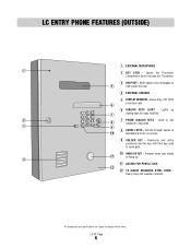
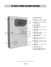
... STAINLESS STEEL DOOR Heavy-duty and weather resistant. Pressed when user wants 11 to dial 8 residents / keycodes 3 9 8 SCROLL KEYS - Residents and utility personnel use this key with their key code to access the Processor. 3 HELP KEY - With digital voice messages to change... without notice. Heavy-duty, 3/8" thick protective lens. 6 6 DIALING KEYS LIGHT - Scrolls through names in 10 alphabetical order on screen. 9 ...
... STAINLESS STEEL DOOR Heavy-duty and weather resistant. Pressed when user wants 11 to dial 8 residents / keycodes 3 9 8 SCROLL KEYS - Residents and utility personnel use this key with their key code to access the Processor. 3 HELP KEY - With digital voice messages to change... without notice. Heavy-duty, 3/8" thick protective lens. 6 6 DIALING KEYS LIGHT - Scrolls through names in 10 alphabetical order on screen. 9 ...
Dial Code LC and VF Series Manual
Page 8
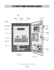
LC/VF Page 7 VF ENTRY PHONE FEATURES (INSIDE) Mounting Holes (4) Processor Key Release / Lock VF Display Processor Unit Dialing Keys Programming Keys Parallel Port Memory Card Memory Card Slot Memory Card Release Buttons Processor Power Switch Microphone Display Hood Display Window Stainless Steel Door Key Lock External Keypad POWER GATE RELAY DOOR RELAY Surge Suppressor Terminal Board Postal Lock Setup External Speaker All components and specifications are subject to change without notice.
LC/VF Page 7 VF ENTRY PHONE FEATURES (INSIDE) Mounting Holes (4) Processor Key Release / Lock VF Display Processor Unit Dialing Keys Programming Keys Parallel Port Memory Card Memory Card Slot Memory Card Release Buttons Processor Power Switch Microphone Display Hood Display Window Stainless Steel Door Key Lock External Keypad POWER GATE RELAY DOOR RELAY Surge Suppressor Terminal Board Postal Lock Setup External Speaker All components and specifications are subject to change without notice.
Dial Code LC and VF Series Manual
Page 9
... 10 UNLOCK KEY - Used to access the Processor. 6 3 HELP KEY - With digital voice messages to hang up 9 dialing keys for easy visibility. 3 10 8 PHONE DIALING KEYS - Pressed when user wants 13 to 5 help guide the user. 4 EXTERNAL SPEAKER 5 DISPLAY WINDOW - Residents and ...utility personnel use this key with their key code 12 to change without notice. Heavy-duty, 3/8" thick protective lens. 7 6 DISPLAY ...
... 10 UNLOCK KEY - Used to access the Processor. 6 3 HELP KEY - With digital voice messages to hang up 9 dialing keys for easy visibility. 3 10 8 PHONE DIALING KEYS - Pressed when user wants 13 to 5 help guide the user. 4 EXTERNAL SPEAKER 5 DISPLAY WINDOW - Residents and ...utility personnel use this key with their key code 12 to change without notice. Heavy-duty, 3/8" thick protective lens. 7 6 DISPLAY ...
Dial Code LC and VF Series Manual
Page 10
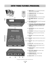
Displays information and instructions, two lines at a time. 8 DIRECTION KEYS - Works like standard keyboard to surge suppressor terminal board. 17 INPUT/OUTPUT CONNECTOR - Connects to type in programming or user modes. 14 SCROLL KEYS - Connects to change without notice. Used for RS485 devices. 3 POWER ON/OFF SWITCH 4 CARD RELEASE BUTTONS - Press this key to go back to surge suppressor terminal board. 19 PARALLEL PORT - Q W E R T Y U I O P 12 SHIFT A S D F G H J K L 13 SPACE BAR Z X C V B N M ' BACK SPACE 15 13 HELP KEY - Connects to the ...
Displays information and instructions, two lines at a time. 8 DIRECTION KEYS - Works like standard keyboard to surge suppressor terminal board. 17 INPUT/OUTPUT CONNECTOR - Connects to type in programming or user modes. 14 SCROLL KEYS - Connects to change without notice. Used for RS485 devices. 3 POWER ON/OFF SWITCH 4 CARD RELEASE BUTTONS - Press this key to go back to surge suppressor terminal board. 19 PARALLEL PORT - Q W E R T Y U I O P 12 SHIFT A S D F G H J K L 13 SPACE BAR Z X C V B N M ' BACK SPACE 15 13 HELP KEY - Connects to the ...
Dial Code LC and VF Series Manual
Page 11
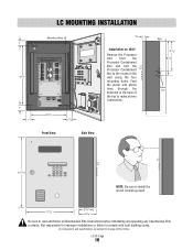
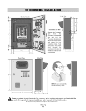
... DOOR RELAY 8 3/4" 1 1/2" 3/4" Installation on Wall Remove the Processor Unit from the Processor Containment Box and bolt the Processor Containment Box to comply with local building codes. All components and specifications are subject to make all Chamberlain Elite instructions before installating and operating any Chamberlain Elite products. Feed the power and phone...
... DOOR RELAY 8 3/4" 1 1/2" 3/4" Installation on Wall Remove the Processor Unit from the Processor Containment Box and bolt the Processor Containment Box to comply with local building codes. All components and specifications are subject to make all Chamberlain Elite instructions before installating and operating any Chamberlain Elite products. Feed the power and phone...
Dial Code LC and VF Series Manual
Page 12
... If unit is not grounded lightning damage wi l occur Please refer to he owners manual for improper installations or failure to comply with local building codes. All components and specifications are subject to make all Chamberlain Elite instructions before installating and operating any Chamberlain Elite products. Side View Wall 6 7/8" 8 1/4" Knock Outs...
... If unit is not grounded lightning damage wi l occur Please refer to he owners manual for improper installations or failure to comply with local building codes. All components and specifications are subject to make all Chamberlain Elite instructions before installating and operating any Chamberlain Elite products. Side View Wall 6 7/8" 8 1/4" Knock Outs...
Dial Code LC and VF Series Manual
Page 13
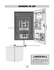
Each time access is granted, the VCR Relay is properly grounded. LC/VF Page 12 Refer to "Grounding the Unit" and " Earth Ground Rod Installation" sections. 9 POWER LED: Indicates Phone system has 12 Vac power. 10 GATE RELAY LED: Indicates gate relay is activated. 11 DOOR RELAY LED: Indicates door relay is not grounded, lightning damage will occur. The provided "chassis ground" wire must be connected to the ground rod. Activates gate relay using gate strike time. 8 CHASSIS GROUND: Entry Phone MUST be properly grounded. eliteentryphone.com MADE IN USA 9 POWER GATE 10 RELAY...
Each time access is granted, the VCR Relay is properly grounded. LC/VF Page 12 Refer to "Grounding the Unit" and " Earth Ground Rod Installation" sections. 9 POWER LED: Indicates Phone system has 12 Vac power. 10 GATE RELAY LED: Indicates gate relay is activated. 11 DOOR RELAY LED: Indicates door relay is not grounded, lightning damage will occur. The provided "chassis ground" wire must be connected to the ground rod. Activates gate relay using gate strike time. 8 CHASSIS GROUND: Entry Phone MUST be properly grounded. eliteentryphone.com MADE IN USA 9 POWER GATE 10 RELAY...
Dial Code LC and VF Series Manual
Page 14
If unit is not grounded, lightning damage will occur. eliteentryphone com MADE N USA POWER GATE RELAY DOOR RELAY Ground Rod Refer to the ground rod. The provided "chassis ground" wire must be connected to the owners manual for ground rod installation. If unit is not grounded, lightning damage will occur. Please refer to the ground rod. The provided "chassis ground" wire must be connected to the next page for proper grounding instructions. LC/VF Page 13 It is MANDATORY that this unit is properly grounded. GROUNDING THE UNIT Chassis Ground TEL L NE RS 485 ...
If unit is not grounded, lightning damage will occur. eliteentryphone com MADE N USA POWER GATE RELAY DOOR RELAY Ground Rod Refer to the ground rod. The provided "chassis ground" wire must be connected to the owners manual for ground rod installation. If unit is not grounded, lightning damage will occur. Please refer to the ground rod. The provided "chassis ground" wire must be connected to the next page for proper grounding instructions. LC/VF Page 13 It is MANDATORY that this unit is properly grounded. GROUNDING THE UNIT Chassis Ground TEL L NE RS 485 ...
Dial Code LC and VF Series Manual
Page 15
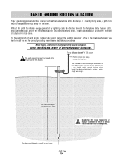
... System The earth ground rod must be directed towards the Telephone Entry System (TES). For the correct diameter, consult the local code LC/VF Page 14 Before digging, contact local underground utility locating companies. Avoid damaging gas, power, or other underground utility lines.... For the correct depth consult the local code Chamberlain Elite is not responsible for improper installation or failure to install the unit for the ground wire. The type and length ...
... System The earth ground rod must be directed towards the Telephone Entry System (TES). For the correct diameter, consult the local code LC/VF Page 14 Before digging, contact local underground utility locating companies. Avoid damaging gas, power, or other underground utility lines.... For the correct depth consult the local code Chamberlain Elite is not responsible for improper installation or failure to install the unit for the ground wire. The type and length ...
Dial Code LC and VF Series Manual
Page 16
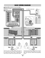
Entry 2 Door Relay Terminal Connection Pedestrian Gate Maglock Conduit Conduit Master Gate Operator (Strike Open Input) Access Door Solenoid OR OR Entry Door Maglock Dial Dial Connect two wires to the secondary gate or door. The door relay will be activated by either pressing 9 on the resident's phone, Door 7-day timer ...
Entry 2 Door Relay Terminal Connection Pedestrian Gate Maglock Conduit Conduit Master Gate Operator (Strike Open Input) Access Door Solenoid OR OR Entry Door Maglock Dial Dial Connect two wires to the secondary gate or door. The door relay will be activated by either pressing 9 on the resident's phone, Door 7-day timer ...
Dial Code LC and VF Series Manual
Page 17
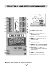
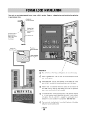
... the hole plug. 2 (Retain nuts and washers) Install the postal lock with Postal Lock on the surge suppressor terminal board. Note that polarity or color coding is not grounded, lightning damage will occur. When the postal lock is engaged, the system's gate relay is activated for proper grounding instructions. LC/VF...
... the hole plug. 2 (Retain nuts and washers) Install the postal lock with Postal Lock on the surge suppressor terminal board. Note that polarity or color coding is not grounded, lightning damage will occur. When the postal lock is engaged, the system's gate relay is activated for proper grounding instructions. LC/VF...
Dial Code LC and VF Series Manual
Page 18
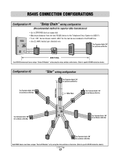
Turn Terminator Switch "ON" for Last Device on Wire Run Turn Terminator Switch "ON" for Last Device on Wire Run Turn Terminator Switch "ON" for Last Device on Wire Run Each RS485 device must have a unique "Device ID Number" set by using the rotary switches on the device. (Refer to specific RS485 Instruction sheets). LC/VF Page 17 Configuration #2 Turn Terminator Switch "ON" for Last Device on Wire Run "Star" wiring configuration Turn Terminator Switch "ON" for Last Device on Wire Run - + Gnd Wire Run Turn Terminator Switch "ON" for Last Device on Wire Run Gnd + - 4000 Ft...
Turn Terminator Switch "ON" for Last Device on Wire Run Turn Terminator Switch "ON" for Last Device on Wire Run Turn Terminator Switch "ON" for Last Device on Wire Run Each RS485 device must have a unique "Device ID Number" set by using the rotary switches on the device. (Refer to specific RS485 Instruction sheets). LC/VF Page 17 Configuration #2 Turn Terminator Switch "ON" for Last Device on Wire Run "Star" wiring configuration Turn Terminator Switch "ON" for Last Device on Wire Run - + Gnd Wire Run Turn Terminator Switch "ON" for Last Device on Wire Run Gnd + - 4000 Ft...
Dial Code LC and VF Series Manual
Page 19
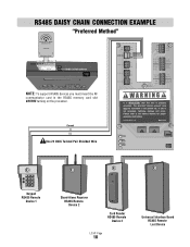
RS485 DAISY CHAIN CONNECTION EXAMPLE "Preferred Method" Remote Access RS485 COMMUNICATOR CARD capacity Elite Entry Phone Main Me Card Slot RS485 Memory Card Slot RS485 Card Release Button NOTE: To support RS485 devices you must be connected to the owners manual for proper grounding instructions. Please refer to the ground rod. Ground (-) (+) Use 22 AWG Twisted Pair Shielded Wire TEL LINE RS485 (1) RS485 (2) RS485 (3) RS485 (4) TIP RING (+) (-) GND (+) (-) GND (+) (-) GND (+) (-) GND 12V AC/DC POWER INPUT DOOR-NO DOOR-NC DOOR-C GATE-NO GATE-NC GATE-C VCR-NO VCR-C CHASSIS GROUND ...
RS485 DAISY CHAIN CONNECTION EXAMPLE "Preferred Method" Remote Access RS485 COMMUNICATOR CARD capacity Elite Entry Phone Main Me Card Slot RS485 Memory Card Slot RS485 Card Release Button NOTE: To support RS485 devices you must be connected to the owners manual for proper grounding instructions. Please refer to the ground rod. Ground (-) (+) Use 22 AWG Twisted Pair Shielded Wire TEL LINE RS485 (1) RS485 (2) RS485 (3) RS485 (4) TIP RING (+) (-) GND (+) (-) GND (+) (-) GND (+) (-) GND 12V AC/DC POWER INPUT DOOR-NO DOOR-NC DOOR-C GATE-NO GATE-NC GATE-C VCR-NO VCR-C CHASSIS GROUND ...
Dial Code LC and VF Series Manual
Page 20
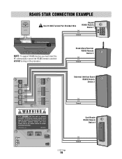
RS485 STAR CONNECTION EXAMPLE Remote Access RS485 COMMUNICATOR CARD capacity Elite Entry Phone Main M ard Slot RS485 Memory Card Slot Use 22 AWG Twisted Pair Shielded Wire Keypad RS485 Remote Device 1 (+) (-) Ground RS485 Card Release Button NOTE: To support RS485 devices you must be connected to the owners manual for proper grounding instructions. The provided "chassis ground" wire must insert the RF communicator card in the RS485 memory card slot BEFORE turning on the processor. Stand-Alone Receiver RS485 Remote Device 2 (+) (-) Ground TEL LINE RS485 (1) RS485 (2) RS485 (3)...
RS485 STAR CONNECTION EXAMPLE Remote Access RS485 COMMUNICATOR CARD capacity Elite Entry Phone Main M ard Slot RS485 Memory Card Slot Use 22 AWG Twisted Pair Shielded Wire Keypad RS485 Remote Device 1 (+) (-) Ground RS485 Card Release Button NOTE: To support RS485 devices you must be connected to the owners manual for proper grounding instructions. The provided "chassis ground" wire must insert the RF communicator card in the RS485 memory card slot BEFORE turning on the processor. Stand-Alone Receiver RS485 Remote Device 2 (+) (-) Ground TEL LINE RS485 (1) RS485 (2) RS485 (3)...