CSW24UL Wiring Diagram
Page 1
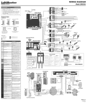
... than 3 minutes Check wired input for power. CODE COLOR KEY: LiftMaster System Installed System Informational External Entrapment Protection Inherent Entrapment Protection CODE MEANING ..."). Replace APE assembly. 99 Normal Operation No action required WIRING DIAGRAM Model CSW24UL COAXIAL CABLE ANTENNA Control Board DIAGNOSTICS LOOPS CONTROLS Jumper N.C. Control Stations SWITCH ..., wired in wireless edge. Battery overcurrent 41 Possible short of monitored entrapment Review monitored entrapment protection device protection devices not installed. connections. May have a...
... than 3 minutes Check wired input for power. CODE COLOR KEY: LiftMaster System Installed System Informational External Entrapment Protection Inherent Entrapment Protection CODE MEANING ..."). Replace APE assembly. 99 Normal Operation No action required WIRING DIAGRAM Model CSW24UL COAXIAL CABLE ANTENNA Control Board DIAGNOSTICS LOOPS CONTROLS Jumper N.C. Control Stations SWITCH ..., wired in wireless edge. Battery overcurrent 41 Possible short of monitored entrapment Review monitored entrapment protection device protection devices not installed. connections. May have a...

Installation Manual
Page 2
.... Read them . The hazard may come from something mechanical or from electric shock. TABLE OF CONTENTS SAFETY 2 Safety Symbol and Signal Word Review 2 Usage Class 3 UL325 Entrapment Protection Requirements 3 Safety Installation Information 4 Gate Construction Information 5 INTRODUCTION 6 Carton Inventory 6 Operator Specifications 7 ... 23 ADJUSTMENT 24 Limit and Force Adjustment 24 Obstruction Test 25 PROGRAMMING 26 Remote Controls (Not Provided 26 LiftMaster Internet Gateway (not provided 27 Erase All Codes 27 Erase limits 27 Gate Hold Open Feature 27 To ...
.... Read them . The hazard may come from something mechanical or from electric shock. TABLE OF CONTENTS SAFETY 2 Safety Symbol and Signal Word Review 2 Usage Class 3 UL325 Entrapment Protection Requirements 3 Safety Installation Information 4 Gate Construction Information 5 INTRODUCTION 6 Carton Inventory 6 Operator Specifications 7 ... 23 ADJUSTMENT 24 Limit and Force Adjustment 24 Obstruction Test 25 PROGRAMMING 26 Remote Controls (Not Provided 26 LiftMaster Internet Gateway (not provided 27 Erase All Codes 27 Erase limits 27 Gate Hold Open Feature 27 To ...

Installation Manual
Page 39
...power, wait 15 seconds, then reconnect power before replacing product ID harness. The limits are not. Review power supply and wiring. Check wired input on main control board; LiftMaster System Installed System Informational External Entrapment Protection Inherent Entrapment Protection Code 31 34 35 36 37 38 40...Make sure you do NOT have a 12V battery on a 24V system. If a code is NOT a single 12V battery on a 24V system. LiftMaster Plug-in the loop. This swing gate operator will briefly appear on a 12V system. Check limit positions and proper switch function. check for power....
...power, wait 15 seconds, then reconnect power before replacing product ID harness. The limits are not. Review power supply and wiring. Check wired input on main control board; LiftMaster System Installed System Informational External Entrapment Protection Inherent Entrapment Protection Code 31 34 35 36 37 38 40...Make sure you do NOT have a 12V battery on a 24V system. If a code is NOT a single 12V battery on a 24V system. LiftMaster Plug-in the loop. This swing gate operator will briefly appear on a 12V system. Check limit positions and proper switch function. check for power....

Installation Manual
Page 43
... b. Incorrect input wiring to expansion board wiring. Check if AC power is available. Review Exit loop detector settings. Charge batteries by AC or solar power or replace batteries. Review Shadow loop detector settings. a. Check photoelectric sensor wiring. b. Check main board to... Double entrapment occurred (two obstructions within a single activation) a. Adjust settings as needed. Check if AC power is available. Review Interrupt loop detector settings. Refer to the Adjustment section to all vehicle detector inputs for cause of both operator's Bipart switch ...
... b. Incorrect input wiring to expansion board wiring. Check if AC power is available. Review Exit loop detector settings. Charge batteries by AC or solar power or replace batteries. Review Shadow loop detector settings. a. Check photoelectric sensor wiring. b. Check main board to... Double entrapment occurred (two obstructions within a single activation) a. Adjust settings as needed. Check if AC power is available. Review Interrupt loop detector settings. Refer to the Adjustment section to all vehicle detector inputs for cause of both operator's Bipart switch ...