
Installation Manual
Page 2
... 9 Install the Cover 22 ADJUSTMENT 23 Limit and Force Adjustment 23 Obstruction Test 24 PROGRAMMING 25 Remote Controls (Not Provided 25 LiftMaster Internet Gateway (not provided 26 Erase All Codes 26 Erase Limits 26 Constant Pressure Override (CPO 26 Gate Hold Open Feature 26...Drive Train 36 TROUBLESHOOTING 37 Diagnostic Codes 37 Diagnostic Codes Table 38 Control Board LEDs 40 Troubleshooting Chart 41 APPENDIX 44 Step 6 Solar Panel(s 44 SAMS Wiring With Relays Not Energized 48 Dual Gate Settings 48 Limit Setup With a Remote Control 49 WIRING DIAGRAM ...
... 9 Install the Cover 22 ADJUSTMENT 23 Limit and Force Adjustment 23 Obstruction Test 24 PROGRAMMING 25 Remote Controls (Not Provided 25 LiftMaster Internet Gateway (not provided 26 Erase All Codes 26 Erase Limits 26 Constant Pressure Override (CPO 26 Gate Hold Open Feature 26...Drive Train 36 TROUBLESHOOTING 37 Diagnostic Codes 37 Diagnostic Codes Table 38 Control Board LEDs 40 Troubleshooting Chart 41 APPENDIX 44 Step 6 Solar Panel(s 44 SAMS Wiring With Relays Not Energized 48 Dual Gate Settings 48 Limit Setup With a Remote Control 49 WIRING DIAGRAM ...
Installation Manual
Page 7
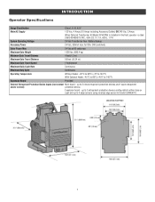
.../480/575 VAC, 4.8/4.2/2.1/1.7 A, 60 Hz, 1 PH System Operating Voltage 24 Vdc Transformer Run / Battery Backup Accessory Power 24 Vdc, 500mA max. for ON + SW (switched) Solar Power Max 24 Vdc at 60 watts max. up to 3 entrapment protection devices configurable to either close or open and up to 2 close entrapment protection...
.../480/575 VAC, 4.8/4.2/2.1/1.7 A, 60 Hz, 1 PH System Operating Voltage 24 Vdc Transformer Run / Battery Backup Accessory Power 24 Vdc, 500mA max. for ON + SW (switched) Solar Power Max 24 Vdc at 60 watts max. up to 3 entrapment protection devices configurable to either close or open and up to 2 close entrapment protection...

Installation Manual
Page 16
...l ALL power wiring should be visible and clearly l Disconnect power at that time the unit may be run the operator without or solar and battery) and locking-out the power via the operator power consulting the wiring diagram. switch. Upon completion of the remote controls... will be reduced and the operator will have to be connected to each operator. SOLAR APPLICATIONS: For solar applications refer to the operator. NOTE: If using an external receiver use shielded wire for the ground wire. Install the earth...
...l ALL power wiring should be visible and clearly l Disconnect power at that time the unit may be run the operator without or solar and battery) and locking-out the power via the operator power consulting the wiring diagram. switch. Upon completion of the remote controls... will be reduced and the operator will have to be connected to each operator. SOLAR APPLICATIONS: For solar applications refer to the operator. NOTE: If using an external receiver use shielded wire for the ground wire. Install the earth...

Installation Manual
Page 19
... plug on the operator. 7. Connect the other end of the red (+) wire from the Solar Harness Kit to the positive (+) terminal on the battery as shown. Reconnect the J15 plug ... and disconnect it. 2. Turn ON AC power to the control board. Connect the white jumper from the Solar Harness Kit between the positive (+) terminal of one end of the other end of the black (-) wire...4. Connect one battery and the negative (-) terminal of the black (-) wire from the Solar Harness Kit to the negative (-) terminal on the battery as shown. Connect the other battery. 3. The 33AH application...
... plug on the operator. 7. Connect the other end of the red (+) wire from the Solar Harness Kit to the positive (+) terminal on the battery as shown. Reconnect the J15 plug ... and disconnect it. 2. Turn ON AC power to the control board. Connect the white jumper from the Solar Harness Kit between the positive (+) terminal of one end of the other end of the black (-) wire...4. Connect one battery and the negative (-) terminal of the black (-) wire from the Solar Harness Kit to the negative (-) terminal on the battery as shown. Connect the other battery. 3. The 33AH application...

Installation Manual
Page 33
..., then turn on AUX RELAY 1 to their appropriate positions. Energizes 3 seconds before gate motion and remains energized during gate motion. Energizes when AC power or solar power is 163,000.). Red/green light functionality, see below . The Expansion Board's 1, 2, and 3 LEDs will turn off . Use with SAMS (Sequenced Access Management System...
..., then turn on AUX RELAY 1 to their appropriate positions. Energizes 3 seconds before gate motion and remains energized during gate motion. Energizes when AC power or solar power is 163,000.). Red/green light functionality, see below . The Expansion Board's 1, 2, and 3 LEDs will turn off . Use with SAMS (Sequenced Access Management System...

Installation Manual
Page 35
...in accordance with gate controls. l ALWAYS keep people and objects away from children. l If lubricating chain, use ONLY LiftMaster part 29-NP712 for proper operation Inspect all power (AC, solar, battery) to service. Read the owner's manual. l Activate gate ONLY when it still complies with an object ...gate MUST reverse on Have a qualified service person make repairs to adjust and retest the gate operator properly can be performed by a LiftMaster professional. After adjusting the force or the limit of FIRE or INJURY to the control board and DOES NOT turn off AC power to...
...in accordance with gate controls. l ALWAYS keep people and objects away from children. l If lubricating chain, use ONLY LiftMaster part 29-NP712 for proper operation Inspect all power (AC, solar, battery) to service. Read the owner's manual. l Activate gate ONLY when it still complies with an object ...gate MUST reverse on Have a qualified service person make repairs to adjust and retest the gate operator properly can be performed by a LiftMaster professional. After adjusting the force or the limit of FIRE or INJURY to the control board and DOES NOT turn off AC power to...

Installation Manual
Page 36
...Batteries will beep 3 times with a command if the battery is low. Two 33AH batteries (A12330SGLPK), with two 7AH batteries. The operator comes with Solar Harness Kit (K94-37236) may be tightened. The operator alarm will degrade over time depending on the operator will stretch and need to be used... in extremely cold temperatures. Drive Train Over time, the drive chain on temperature and usage. Use only LiftMaster part 29-NP712 for every 10 feet of properly. The batteries contain lead and need to be replaced every 3 years. NOTE: The chain...
...Batteries will beep 3 times with a command if the battery is low. Two 33AH batteries (A12330SGLPK), with two 7AH batteries. The operator comes with Solar Harness Kit (K94-37236) may be tightened. The operator alarm will degrade over time depending on the operator will stretch and need to be used... in extremely cold temperatures. Drive Train Over time, the drive chain on temperature and usage. Use only LiftMaster part 29-NP712 for every 10 feet of properly. The batteries contain lead and need to be replaced every 3 years. NOTE: The chain...
Installation Manual
Page 37
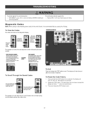
... up to the control board, it is recommended that you unplug the J15 plug. For continued protection against fire and electrocution: l DISCONNECT power (AC or solar and battery) BEFORE installing or servicing operator. The display will start saving over the oldest codes as new codes occur. 37 Diagnostic Codes NOTE: When...
... up to the control board, it is recommended that you unplug the J15 plug. For continued protection against fire and electrocution: l DISCONNECT power (AC or solar and battery) BEFORE installing or servicing operator. The display will start saving over the oldest codes as new codes occur. 37 Diagnostic Codes NOTE: When...
Installation Manual
Page 40
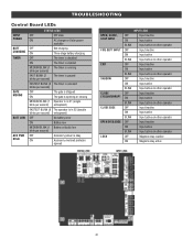
TROUBLESHOOTING Control Board LEDs INPUT OFF POWER ON STATUS LEDS OFF state AC charger or Solar power available BATT OFF CHARGING ON Not charging Three stage battery charging TIMER OFF ON MEDIUM BLINK (1 blink per second) The timer is disabled The ...
TROUBLESHOOTING Control Board LEDs INPUT OFF POWER ON STATUS LEDS OFF state AC charger or Solar power available BATT OFF CHARGING ON Not charging Three stage battery charging TIMER OFF ON MEDIUM BLINK (1 blink per second) The timer is disabled The ...
Installation Manual
Page 41
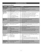
...inputs for a "stuck on " c. Battery voltage must move easily and freely through its entire range, limit to limit. Charge batteries by AC or solar power or replace batteries d. Operator does not respond to a wired control/command (example: Open, Close, SBC, etc.) Operator does not respond to a... limit position b. Charge batteries by AC or solar power or replace batteries 41 b. Repair gate as needed . Check Stop button is not "stuck on battery power only, low or dead batteries e....
...inputs for a "stuck on " c. Battery voltage must move easily and freely through its entire range, limit to limit. Charge batteries by AC or solar power or replace batteries d. Operator does not respond to a wired control/command (example: Open, Close, SBC, etc.) Operator does not respond to a... limit position b. Charge batteries by AC or solar power or replace batteries 41 b. Repair gate as needed . Check Stop button is not "stuck on battery power only, low or dead batteries e....
Installation Manual
Page 42
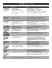
... settings. c. a. Adjust settings as needed. a. Check edge sensor wiring. Press the reset button to OFF. Charge batteries by AC or solar power or replace batteries. Gate closes, but will not open. On dual-gate system, incorrect gate opens first or closes first. Timer-to...on batteries and battery voltage must be 23.0 Vdc or higher. Check if AC power is available. Charge batteries by AC or solar power or replace batteries. Review Shadow loop detector settings. Retest that obstructing photoelectric sensor causes moving gate to OPEN e. If no AC...
... settings. c. a. Adjust settings as needed. a. Check edge sensor wiring. Press the reset button to OFF. Charge batteries by AC or solar power or replace batteries. Gate closes, but will not open. On dual-gate system, incorrect gate opens first or closes first. Timer-to...on batteries and battery voltage must be 23.0 Vdc or higher. Check if AC power is available. Charge batteries by AC or solar power or replace batteries. Review Shadow loop detector settings. Retest that obstructing photoelectric sensor causes moving gate to OPEN e. If no AC...
Installation Manual
Page 43
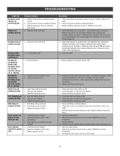
.... a. Battery capacity too low SOLUTIONS a. Check wiring to Switch (SW) Accessory power not working correctly. Add more solar panels b. Solar panels are not getting enough cycles per day. Check that Solenoid is ON b. Check that Maglock has power (do...Maglock not working correctly. Interrupt loop detector c. a. If required, replace wire cable. Reduce the accessory power draw by using LiftMaster low power accessories c. Solenoid wired incorrectly Switched (SW) Accessory power remaining on expansion board. Old batteries d. b. If ...
.... a. Battery capacity too low SOLUTIONS a. Check wiring to Switch (SW) Accessory power not working correctly. Add more solar panels b. Solar panels are not getting enough cycles per day. Check that Solenoid is ON b. Check that Maglock has power (do...Maglock not working correctly. Interrupt loop detector c. a. If required, replace wire cable. Reduce the accessory power draw by using LiftMaster low power accessories c. Solenoid wired incorrectly Switched (SW) Accessory power remaining on expansion board. Old batteries d. b. If ...
Installation Manual
Page 44
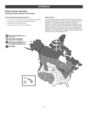
... (Model K94-37236). Local geography and weather conditions may require additional solar panels. Solar powered gate operator installations are based upon the average solar radiation and the temperature effects on batteries in northern climates due to cold weather ... vary based on the map below. Solar panels cannot be used with a solar application. APPENDIX Step 6 Solar Panel(s) SOLAR PANELS ARE NOT PROVIDED. SEE ACCESSORIES Solar Application Requirements l A minimum of six 10W solar panels (Model SP10W12V). Solar Zones Solar panel recommendations are not supported in the...
... (Model K94-37236). Local geography and weather conditions may require additional solar panels. Solar powered gate operator installations are based upon the average solar radiation and the temperature effects on batteries in northern climates due to cold weather ... vary based on the map below. Solar panels cannot be used with a solar application. APPENDIX Step 6 Solar Panel(s) SOLAR PANELS ARE NOT PROVIDED. SEE ACCESSORIES Solar Application Requirements l A minimum of six 10W solar panels (Model SP10W12V). Solar Zones Solar panel recommendations are not supported in the...
Installation Manual
Page 45
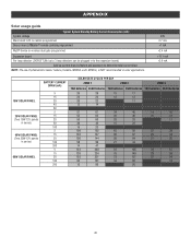
APPENDIX Solar usage guide Typical System Standby Battery Current Consumption (mA) System voltage Main board with no radios programmed One or more LiftMaster® remote controls programmed MyQ® device or wireless dual gate programmed Expansion board Per loop detector LOOPDETLM (up to 3 loop detectors can be plugged ... BATTERY CURRENT DRAW (mA) 5 15 20 40 60 5 15 20 50 100 5 15 20 100 200 5 15 20 100 250 SOLAR GATE CYCLES PER DAY ZONE 1 ZONE 2 ZONE 3 7AH batteries 33AH batteries 7AH batteries 33AH batteries 7AH batteries 33AH batteries 26 28 15 17 22 24 ...
APPENDIX Solar usage guide Typical System Standby Battery Current Consumption (mA) System voltage Main board with no radios programmed One or more LiftMaster® remote controls programmed MyQ® device or wireless dual gate programmed Expansion board Per loop detector LOOPDETLM (up to 3 loop detectors can be plugged ... BATTERY CURRENT DRAW (mA) 5 15 20 40 60 5 15 20 50 100 5 15 20 100 200 5 15 20 100 250 SOLAR GATE CYCLES PER DAY ZONE 1 ZONE 2 ZONE 3 7AH batteries 33AH batteries 7AH batteries 33AH batteries 7AH batteries 33AH batteries 26 28 15 17 22 24 ...
Installation Manual
Page 46
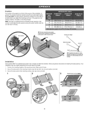
...12 600 (182.9 m) 300 (91.4 m) 200 (61 m) 10 940 (286.5 m) 475 (144.8 m) 315 (96 m) Chart assumes: copper wire, 65°C, 5% drop, 30V nominal Installation Solar panel(s) MUST be mounted using the provided angle bracket facing due south. Mark and drill holes. 2. NOTE: Tall trees or buildings that do not shade... the solar panel(s) in the summer could shade the solar panel(s) during the winter months when the sun sits lower in an area clear of the installation. Below are general ...
...12 600 (182.9 m) 300 (91.4 m) 200 (61 m) 10 940 (286.5 m) 475 (144.8 m) 315 (96 m) Chart assumes: copper wire, 65°C, 5% drop, 30V nominal Installation Solar panel(s) MUST be mounted using the provided angle bracket facing due south. Mark and drill holes. 2. NOTE: Tall trees or buildings that do not shade... the solar panel(s) in the summer could shade the solar panel(s) during the winter months when the sun sits lower in an area clear of the installation. Below are general ...
Installation Manual
Page 47
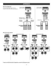
Wire the Batteries Solar panel applications require the Solar Harness Kit model K94-37236, see Accessories. APPENDIX Wire the solar panels Proceed to the Dual Gate section (if applicable) or proceed to the Adjustment section. 47
Wire the Batteries Solar panel applications require the Solar Harness Kit model K94-37236, see Accessories. APPENDIX Wire the solar panels Proceed to the Dual Gate section (if applicable) or proceed to the Adjustment section. 47

Installation Manual
Page 50
WIRING DIAGRAM To protect against fire: l Replace ONLY with fuse of same type and rating. 50 For continued protection against fire and electrocution: l DISCONNECT power (AC or solar and battery) BEFORE installing or servicing operator.
WIRING DIAGRAM To protect against fire: l Replace ONLY with fuse of same type and rating. 50 For continued protection against fire and electrocution: l DISCONNECT power (AC or solar and battery) BEFORE installing or servicing operator.

Installation Manual
Page 53
... board. Ideal for 12 Vdc operators. Model K10-34758-2 Universal solar wire harness kit For 7AH and 33AH applications. ACCESSORIES Miscellaneous Post-mounting plate For post-mounting models CSL24UL, CSW24UL CSW200UL and SL3000UL commercial gate operators. Posts not included. Model 86LM LiftMaster® internet gateway Internet enabled accessory which connects to the computer...
... board. Ideal for 12 Vdc operators. Model K10-34758-2 Universal solar wire harness kit For 7AH and 33AH applications. ACCESSORIES Miscellaneous Post-mounting plate For post-mounting models CSL24UL, CSW24UL CSW200UL and SL3000UL commercial gate operators. Posts not included. Model 86LM LiftMaster® internet gateway Internet enabled accessory which connects to the computer...
CSL24UL Wiring Diagram
Page 1
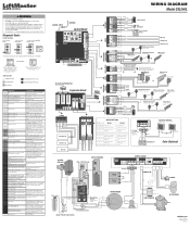
...Limit (Arm 1) 39 Hard Stop Limit (Arm 2) Limit may be at open or close cycle OR Solar Panels (Optional) 20W minimum - 60W maximum, wired in the manual. 93 RPM / STALL Reversal ...To Pin 1 Run To Pin 5 Stop/Reset RESET SWITCH APS ENCODER Motor LiftMaster.com © 2018, LiftMaster All Rights Reserved 01-39240-2 May be compliant with UL325 and industry safety ...set limits. Replace APE assembly. 99 Normal Operation No action required WIRING DIAGRAM Model CSL24UL COAXIAL CABLE ANTENNA Control Board DIAGNOSTICS LOOPS CONTROLS Jumper N.C. If so, erase limits,...
...Limit (Arm 1) 39 Hard Stop Limit (Arm 2) Limit may be at open or close cycle OR Solar Panels (Optional) 20W minimum - 60W maximum, wired in the manual. 93 RPM / STALL Reversal ...To Pin 1 Run To Pin 5 Stop/Reset RESET SWITCH APS ENCODER Motor LiftMaster.com © 2018, LiftMaster All Rights Reserved 01-39240-2 May be compliant with UL325 and industry safety ...set limits. Replace APE assembly. 99 Normal Operation No action required WIRING DIAGRAM Model CSL24UL COAXIAL CABLE ANTENNA Control Board DIAGNOSTICS LOOPS CONTROLS Jumper N.C. If so, erase limits,...
CSL24UL Product Data Sheet
Page 1
... and higher SPECIFICATIONS OPERATOR SPEED 12 in synthetic oil bath CHAIN #41 black oxide (60 ft. Reference detailed solar chart on product page at LiftMaster.com DIAGNOSTIC DISPLAY LED diagnostic display WIRELESS DUAL-GATE COMMUNICATION Eliminates expensive conduit costs and unsightly driveway scars POSILOCK®...second POWER 120V/230VAC single phase ACCESSORY POWER 24VDC, 500mA output; switched and unswitched power OPERATOR WEIGHT 140 lbs. CSL24UL SLIDE GATE OPERATOR SECTION 32 31 00 KEY FEATURES BATTERY BACKUP Up to 24 days of AC power or battery ...
... and higher SPECIFICATIONS OPERATOR SPEED 12 in synthetic oil bath CHAIN #41 black oxide (60 ft. Reference detailed solar chart on product page at LiftMaster.com DIAGNOSTIC DISPLAY LED diagnostic display WIRELESS DUAL-GATE COMMUNICATION Eliminates expensive conduit costs and unsightly driveway scars POSILOCK®...second POWER 120V/230VAC single phase ACCESSORY POWER 24VDC, 500mA output; switched and unswitched power OPERATOR WEIGHT 140 lbs. CSL24UL SLIDE GATE OPERATOR SECTION 32 31 00 KEY FEATURES BATTERY BACKUP Up to 24 days of AC power or battery ...


