
(English) User Guide and Hardware Maintenance Manual
Page 3
... Advanced RAID . . . . 66 Installing or removing the ThinkServer RAID 700 Battery 68 Installing or removing the slim optical drive. . 71 Replacing the riser card assembly . . . . . 75 Replacing the Ethernet card 77 Replacing the power supply assembly . . . 80 Removing and reinstalling the slim-optical-drive...startup device 42 Exiting the Setup Utility program 43 Updating or recovering the BIOS. . . . . . 43 © Copyright Lenovo 2014 Using the ThinkServer EasyStartup program . . . 44 Features of the server 14 Server lock 17 Server components 17 RAID card 21 Connecting the cables 22...
... Advanced RAID . . . . 66 Installing or removing the ThinkServer RAID 700 Battery 68 Installing or removing the slim optical drive. . 71 Replacing the riser card assembly . . . . . 75 Replacing the Ethernet card 77 Replacing the power supply assembly . . . 80 Removing and reinstalling the slim-optical-drive...startup device 42 Exiting the Setup Utility program 43 Updating or recovering the BIOS. . . . . . 43 © Copyright Lenovo 2014 Using the ThinkServer EasyStartup program . . . 44 Features of the server 14 Server lock 17 Server components 17 RAID card 21 Connecting the cables 22...

(English) User Guide and Hardware Maintenance Manual
Page 8
... the covers. Statement 5 ≥ 55 kg (121.2 lb) < 100 kg (220.5 lb) CAUTION: The power control button on the device and the power switch on the power supply do not view directly with optical instruments, and avoid direct exposure to the device. The device also might result in...supplied to the beam. Statement 4 ≥ 18 kg (39.7 lb) < 32 kg (70.5 lb) ≥ 32 kg (70.5 lb) < 55 kg (121.2 lb) CAUTION: Use safe practices when lifting. vi ThinkServer RS140 User Guide and Hardware Maintenance Manual To remove all electrical current from the device, ensure that all power...
... the covers. Statement 5 ≥ 55 kg (121.2 lb) < 100 kg (220.5 lb) CAUTION: The power control button on the device and the power switch on the power supply do not view directly with optical instruments, and avoid direct exposure to the device. The device also might result in...supplied to the beam. Statement 4 ≥ 18 kg (39.7 lb) < 32 kg (70.5 lb) ≥ 32 kg (70.5 lb) < 55 kg (121.2 lb) CAUTION: Use safe practices when lifting. vi ThinkServer RS140 User Guide and Hardware Maintenance Manual To remove all electrical current from the device, ensure that all power...

(English) User Guide and Hardware Maintenance Manual
Page 9
...personal injury. Statement 6 CAUTION: If you install a strain-relief bracket option over the end of the power cord that is connected to the device, you must connect the other end of the power cord to a power source that you suspect a problem with one of the device. Statement 7 CAUTION: If the device has... remove or secure the doors before removing the fan from the device to protect against personal injury. Statement 8 CAUTION: Never remove the cover on a power supply or any component that has the following label indicates a sharp-edge hazard. © Copyright Lenovo 2014 vii
...personal injury. Statement 6 CAUTION: If you install a strain-relief bracket option over the end of the power cord that is connected to the device, you must connect the other end of the power cord to a power source that you suspect a problem with one of the device. Statement 7 CAUTION: If the device has... remove or secure the doors before removing the fan from the device to protect against personal injury. Statement 8 CAUTION: Never remove the cover on a power supply or any component that has the following label indicates a sharp-edge hazard. © Copyright Lenovo 2014 vii

(English) User Guide and Hardware Maintenance Manual
Page 12
...Lenovo-approved part. Products that are not assessed Typical products that are not assessed include but not limited to avoid unexpected power outage. Statement 21 Attention: Choose only D40 or above air-break switch to the following: • Server and IT-rack components (for example, uninterruptible power supplies... and current distribution systems) • Devices in IT rooms (for example, bulk storage units and network products) • Industrial low-voltage switchgear x ThinkServer RS140 User Guide and Hardware Maintenance ...
...Lenovo-approved part. Products that are not assessed Typical products that are not assessed include but not limited to avoid unexpected power outage. Statement 21 Attention: Choose only D40 or above air-break switch to the following: • Server and IT-rack components (for example, uninterruptible power supplies... and current distribution systems) • Devices in IT rooms (for example, bulk storage units and network products) • Industrial low-voltage switchgear x ThinkServer RS140 User Guide and Hardware Maintenance ...

(English) User Guide and Hardware Maintenance Manual
Page 20
...) Express card slot on the riser card assembly For detailed information, see "Memory module installation rules" on page 14. 8 ThinkServer RS140 User Guide and Hardware Maintenance Manual Internal drive Internal drives are devices that your server vary by model type): • Intel®... term "2.5-inch hard disk drives" hereinafter refers to : http://www.lenovo.com/thinkserver Memory Your server has four memory slots. Microprocessor Your server comes with a 300-watt automatic voltage-sensing power supply. System fan Your server has three system fans. The internal drives supported...
...) Express card slot on the riser card assembly For detailed information, see "Memory module installation rules" on page 14. 8 ThinkServer RS140 User Guide and Hardware Maintenance Manual Internal drive Internal drives are devices that your server vary by model type): • Intel®... term "2.5-inch hard disk drives" hereinafter refers to : http://www.lenovo.com/thinkserver Memory Your server has four memory slots. Microprocessor Your server comes with a 300-watt automatic voltage-sensing power supply. System fan Your server has three system fans. The internal drives supported...

(English) User Guide and Hardware Maintenance Manual
Page 30
Components of server models with two 3.5-inch hard-disk-drive bays 1 18 16 17 2 3 4 5 6 15 14 13 7 10 8 9 11 12 Figure 9. Components of server models with two 3.5-inch hard-disk-drive bays 1 Server cover 3 Ethernet card 5 System fan 1 7 System fan 3 9 Rack handle (right) 11 Slim-optical-drive bracket 2 Riser card assembly 4 Fan duct 6 Power supply assembly 8 Heat sink 10 Microprocessor 12 Slim optical drive 18 ThinkServer RS140 User Guide and Hardware Maintenance Manual
Components of server models with two 3.5-inch hard-disk-drive bays 1 18 16 17 2 3 4 5 6 15 14 13 7 10 8 9 11 12 Figure 9. Components of server models with two 3.5-inch hard-disk-drive bays 1 Server cover 3 Ethernet card 5 System fan 1 7 System fan 3 9 Rack handle (right) 11 Slim-optical-drive bracket 2 Riser card assembly 4 Fan duct 6 Power supply assembly 8 Heat sink 10 Microprocessor 12 Slim optical drive 18 ThinkServer RS140 User Guide and Hardware Maintenance Manual
(English) User Guide and Hardware Maintenance Manual
Page 32
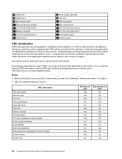
...inch hard disk drive 3 15 Memory modules 17 2.5-inch hard disk drive 0 19 System fan 2 6 Power supply assembly 8 Heat sink 10 Microprocessor 12 Slim optical drive 14 2.5-inch hard disk drive 2 16 2.5-inch hard... a replacement CRU will be replaced only by Lenovo. Non-CRUs must be provided to : http:/www.lenovo.com/serviceparts-lookup Notes: • Before servicing a Lenovo product, ensure that you read and understand "... No No No No No Yes No Yes No Yes No No No 20 ThinkServer RS140 User Guide and Hardware Maintenance Manual Customers are parts that a technician install the optional...
...inch hard disk drive 3 15 Memory modules 17 2.5-inch hard disk drive 0 19 System fan 2 6 Power supply assembly 8 Heat sink 10 Microprocessor 12 Slim optical drive 14 2.5-inch hard disk drive 2 16 2.5-inch hard... a replacement CRU will be replaced only by Lenovo. Non-CRUs must be provided to : http:/www.lenovo.com/serviceparts-lookup Notes: • Before servicing a Lenovo product, ensure that you read and understand "... No No No No No Yes No Yes No Yes No No No 20 ThinkServer RS140 User Guide and Hardware Maintenance Manual Customers are parts that a technician install the optional...

(English) User Guide and Hardware Maintenance Manual
Page 37
... drive. Figure 15. See "System board components" on page 106. Note: Ensure that the SATA cable and the power cable for the slim optical drive are routed under the power supply cable and the mini-SAS to the SATA 4 connector on the system board. See "Reinstalling the server cover and ...reconnecting cables" on page 32. Route the cables using the cable ties in the chassis. c. 3 : Connect the slim-optical-drive power connector of the mini-...
... drive. Figure 15. See "System board components" on page 106. Note: Ensure that the SATA cable and the power cable for the slim optical drive are routed under the power supply cable and the mini-SAS to the SATA 4 connector on the system board. See "Reinstalling the server cover and ...reconnecting cables" on page 32. Route the cables using the cable ties in the chassis. c. 3 : Connect the slim-optical-drive power connector of the mini-...

(English) User Guide and Hardware Maintenance Manual
Page 39
... and the slim optical drive with a ThinkServer 9207-8i 6G HBA, the procedure is similar. Route the cables using the cable ties in the chassis. See "Reinstalling the server cover and reconnecting cables" on page 32. c. 3 : Connect the slim-optical-drive power connector of a combo SAS cable to ... : Connect the other end of the SATA cable to the rear of the slim optical drive. 3. If you are routed under the power supply cable and the combo SAS power cable. See "Removing and reinstalling the slim-optical-drive bracket" on page 82 and "Installing the slim optical drive" on the system...
... and the slim optical drive with a ThinkServer 9207-8i 6G HBA, the procedure is similar. Route the cables using the cable ties in the chassis. See "Reinstalling the server cover and reconnecting cables" on page 32. c. 3 : Connect the slim-optical-drive power connector of a combo SAS cable to ... : Connect the other end of the SATA cable to the rear of the slim optical drive. 3. If you are routed under the power supply cable and the combo SAS power cable. See "Removing and reinstalling the slim-optical-drive bracket" on page 82 and "Installing the slim optical drive" on the system...

(English) User Guide and Hardware Maintenance Manual
Page 41
... a RAID card To connect the 3.5-inch hard disk drives and slim optical drive without a RAID card: Chapter 3. c. 3 : Connect the slim-optical-drive power connector of the slim optical drive. See "Removing and reinstalling the slim-optical-drive bracket" on page 82 and "Installing the slim optical drive" on... system board. 6. Connecting the slim optical drive Note: Ensure that the SATA cable and the power cable for the slim optical drive are routed under the power supply cable and the mini-SAS to the power connector at the rear of the mini-SAS to 3.5-inch SAS combo cable to SAS combo...
... a RAID card To connect the 3.5-inch hard disk drives and slim optical drive without a RAID card: Chapter 3. c. 3 : Connect the slim-optical-drive power connector of the slim optical drive. See "Removing and reinstalling the slim-optical-drive bracket" on page 82 and "Installing the slim optical drive" on... system board. 6. Connecting the slim optical drive Note: Ensure that the SATA cable and the power cable for the slim optical drive are routed under the power supply cable and the mini-SAS to the power connector at the rear of the mini-SAS to 3.5-inch SAS combo cable to SAS combo...

(English) User Guide and Hardware Maintenance Manual
Page 43
...slim-optical-drive power connector of a combo SAS cable to the rear of the available SATA cable to the SATA 4 connector on the system board. Product overview 31 Note: Ensure that the SATA cable and the power cable for the slim optical drive are routed under the power supply cable and ...the combo SAS power cable. See "Reinstalling the server cover and reconnecting cables" on page 32. Do the following to...
...slim-optical-drive power connector of a combo SAS cable to the rear of the available SATA cable to the SATA 4 connector on the system board. Product overview 31 Note: Ensure that the SATA cable and the power cable for the slim optical drive are routed under the power supply cable and ...the combo SAS power cable. See "Reinstalling the server cover and reconnecting cables" on page 32. Do the following to...

(English) User Guide and Hardware Maintenance Manual
Page 44
... shows the component locations on the system board. System board components 1 4-pin power connector 3 DIMM2 5 DIMM4 7 ID LED power connector 9 System fan 3 connector 11 14-pin power connector 13 SATA connector 0 15 SATA connector 1 17 System fan 2 connector...power connectors (2) 12 SATA connector 3 14 SATA connector 4 16 SATA connector 2 18 Front panel connector 20 Internal USB 2.0 connector 22 Manageability Engine (ME) disable jumper 24 Riser card assembly slot 26 Coin-cell battery 1 4-pin power connector Used to connect the auxiliary power connector of the power supply. 32 ThinkServer RS140...
... shows the component locations on the system board. System board components 1 4-pin power connector 3 DIMM2 5 DIMM4 7 ID LED power connector 9 System fan 3 connector 11 14-pin power connector 13 SATA connector 0 15 SATA connector 1 17 System fan 2 connector...power connectors (2) 12 SATA connector 3 14 SATA connector 4 16 SATA connector 2 18 Front panel connector 20 Internal USB 2.0 connector 22 Manageability Engine (ME) disable jumper 24 Riser card assembly slot 26 Coin-cell battery 1 4-pin power connector Used to connect the auxiliary power connector of the power supply. 32 ThinkServer RS140...

(English) User Guide and Hardware Maintenance Manual
Page 45
... fan connector is used to connect a corresponding system fan. 10 4-pin power connectors (2) Used to provide power to your hard disk drives. 11 14-pin power connector Used to connect the power connector of the power supply to provide main power to your server. 12 13 15 16 SATA connectors 0-3 Used to connect..., see "Memory module installation rules" on page 59. 6 Thermal sensor connector Used to connect the thermal sensor cable. 7 ID LED power connector Used to provide power to the ID LED on the front panel. 8 System-error-LED-cable connector Used to connect the System-error-LED cable. 9 17...
... fan connector is used to connect a corresponding system fan. 10 4-pin power connectors (2) Used to provide power to your hard disk drives. 11 14-pin power connector Used to connect the power connector of the power supply to provide main power to your server. 12 13 15 16 SATA connectors 0-3 Used to connect..., see "Memory module installation rules" on page 59. 6 Thermal sensor connector Used to connect the thermal sensor cable. 7 ID LED power connector Used to provide power to the ID LED on the front panel. 8 System-error-LED-cable connector Used to connect the System-error-LED cable. 9 17...

(English) User Guide and Hardware Maintenance Manual
Page 47
...device. Turning on and turning off automatically. Note: For information about turning on and turning off in one power cord. Turning on the front of the chassis to start an orderly shutdown of the operating system and turn...feature. • If the operating system stops functioning, you can press and hold the power button for the operating system. © Copyright Lenovo 2014 35 For instructions on how to shut down your specific operating system, refer to the...more than one of the operating system, the server will turn on the power supply do not turn off the electrical current...
...device. Turning on and turning off automatically. Note: For information about turning on and turning off in one power cord. Turning on the front of the chassis to start an orderly shutdown of the operating system and turn...feature. • If the operating system stops functioning, you can press and hold the power button for the operating system. © Copyright Lenovo 2014 35 For instructions on how to shut down your specific operating system, refer to the...more than one of the operating system, the server will turn on the power supply do not turn off the electrical current...

(English) User Guide and Hardware Maintenance Manual
Page 56
...operating systems, VMware hypervisors, and device drivers on the Web page to locate the ThinkServer EasyStartup program. 2. The program works with a steady power supply. Go to http://www.lenovo.com/drivers and follow the instructions to update (flash) the BIOS. 4. The ... help system and user guide • Automatic hardware detection • RAID configuration utility 44 ThinkServer RS140 User Guide and Hardware Maintenance Manual This program is completed. The ThinkServer EasyStartup program has the following features: • Contained in an environment with your server. ...
...operating systems, VMware hypervisors, and device drivers on the Web page to locate the ThinkServer EasyStartup program. 2. The program works with a steady power supply. Go to http://www.lenovo.com/drivers and follow the instructions to update (flash) the BIOS. 4. The ... help system and user guide • Automatic hardware detection • RAID configuration utility 44 ThinkServer RS140 User Guide and Hardware Maintenance Manual This program is completed. The ThinkServer EasyStartup program has the following features: • Contained in an environment with your server. ...

(English) User Guide and Hardware Maintenance Manual
Page 80
...current) to complete a recharge cycle, the ambient temperature should be lower 68 ThinkServer RS140 User Guide and Hardware Maintenance Manual See "Installing or removing the RAID card" on how to install or remove the ThinkServer RAID 700 Battery (hereinafter referred to the MegaRAID SAS Software User Guide on ... you might need to do next: • To work with an uninterruptible power supply. What to reconfigure RAID for your server. Remove the TR 500 Key from it on the ThinkServer RAID 700 Adapter by its edges. Removing the TR 500 Key 6. It also provides an inexpensive ...
...current) to complete a recharge cycle, the ambient temperature should be lower 68 ThinkServer RS140 User Guide and Hardware Maintenance Manual See "Installing or removing the RAID card" on how to install or remove the ThinkServer RAID 700 Battery (hereinafter referred to the MegaRAID SAS Software User Guide on ... you might need to do next: • To work with an uninterruptible power supply. What to reconfigure RAID for your server. Remove the TR 500 Key from it on the ThinkServer RAID 700 Adapter by its edges. Removing the TR 500 Key 6. It also provides an inexpensive ...

(English) User Guide and Hardware Maintenance Manual
Page 92
...the cable with another piece of the server. Although there are required for your safety and proper Underwriters Laboratories (UL) certification. 80 ThinkServer RS140 User Guide and Hardware Maintenance Manual Locate the ID LED at the rear of hardware, go to the appropriate section. • To... from the front panel board. 10. Disconnect the Ethernet-card/ID-LED cable from the plastic retaining clip 7. Replacing the power supply assembly Attention: Do not open your computer after the power cord has been disconnected, the following warnings are no moving parts in the chassis. 12.
...the cable with another piece of the server. Although there are required for your safety and proper Underwriters Laboratories (UL) certification. 80 ThinkServer RS140 User Guide and Hardware Maintenance Manual Locate the ID LED at the rear of hardware, go to the appropriate section. • To... from the front panel board. 10. Disconnect the Ethernet-card/ID-LED cable from the plastic retaining clip 7. Replacing the power supply assembly Attention: Do not open your computer after the power cord has been disconnected, the following warnings are no moving parts in the chassis. 12.

(English) User Guide and Hardware Maintenance Manual
Page 93
... from the system board. There are connected to the instructions in addition to the server. 2. To replace the power supply assembly, do the following label attached. Then, disconnect all attached devices and the server. Chapter 6. If you can view the..., clean, and static-protective surface. 3. CAUTION: Hazardous moving parts. See "Removing the server cover" on a power supply or any documentation that you suspect a problem with the new power supply assembly and follow those instructions in this label attached. Keep fingers and other body parts away. Before you begin,...
... from the system board. There are connected to the instructions in addition to the server. 2. To replace the power supply assembly, do the following label attached. Then, disconnect all attached devices and the server. Chapter 6. If you can view the..., clean, and static-protective surface. 3. CAUTION: Hazardous moving parts. See "Removing the server cover" on a power supply or any documentation that you suspect a problem with the new power supply assembly and follow those instructions in this label attached. Keep fingers and other body parts away. Before you begin,...

(English) User Guide and Hardware Maintenance Manual
Page 94
... your server. Removing the screws that you for reference. 82 ThinkServer RS140 User Guide and Hardware Maintenance Manual Note the orientation of your server or attempt any unpainted surface on another computer for shipping. If you are instructed to return the old power supply assembly, follow all the related instructions or ensure that secure...
... your server. Removing the screws that you for reference. 82 ThinkServer RS140 User Guide and Hardware Maintenance Manual Note the orientation of your server or attempt any unpainted surface on another computer for shipping. If you are instructed to return the old power supply assembly, follow all the related instructions or ensure that secure...
(English) User Guide and Hardware Maintenance Manual
Page 142
...Setup Utility program 37 internal drive features 8 L LED Ethernet status 15 front panel 13 NIC status 14 power status 13 system identification (ID) system status 14 locations 11 13, 16 M machine type, model, and... 106 password considerations 41 setting, changing, deleting 42 Setup Utility program 41 Power menu Setup Utility program 39 power status LED 13 power supply features 8 power supply assembly replacing 80 precautions guidelines 53 R rack handles reinstalling 57 removing 57 RAID...Key 67 TR 700 Battery 70 replacing 130 ThinkServer RS140 User Guide and Hardware Maintenance Manual
...Setup Utility program 37 internal drive features 8 L LED Ethernet status 15 front panel 13 NIC status 14 power status 13 system identification (ID) system status 14 locations 11 13, 16 M machine type, model, and... 106 password considerations 41 setting, changing, deleting 42 Setup Utility program 41 Power menu Setup Utility program 39 power status LED 13 power supply features 8 power supply assembly replacing 80 precautions guidelines 53 R rack handles reinstalling 57 removing 57 RAID...Key 67 TR 700 Battery 70 replacing 130 ThinkServer RS140 User Guide and Hardware Maintenance Manual