
Hardware Maintenance Manual
Page 4
Removing or replacing a FRU 63 General guidelines 63 Removing the SIM card 64 1010 Lenovo OneLink connector cover . . . . . 65 1020 Battery pack 65 1030 Large bottom cover 66 1040 Small bottom cover 67 1050 Optical drive or blank bezel 68 ... 1080 Wireless WAN card or M.2 solid-state drive . 71 1090 Wireless LAN card 73 1100 Backup battery 74 1110 Thermal fan assembly 75 1120 Keyboard 77 1130 Keyboard bezel 83 1140 Microprocessor 86 1150 System board assembly 87 1160 Card reader with USB connector sub card . 90 1170 DC-in bracket, DC...
Removing or replacing a FRU 63 General guidelines 63 Removing the SIM card 64 1010 Lenovo OneLink connector cover . . . . . 65 1020 Battery pack 65 1030 Large bottom cover 66 1040 Small bottom cover 67 1050 Optical drive or blank bezel 68 ... 1080 Wireless WAN card or M.2 solid-state drive . 71 1090 Wireless LAN card 73 1100 Backup battery 74 1110 Thermal fan assembly 75 1120 Keyboard 77 1130 Keyboard bezel 83 1140 Microprocessor 86 1150 System board assembly 87 1160 Card reader with USB connector sub card . 90 1170 DC-in bracket, DC...
Hardware Maintenance Manual
Page 34
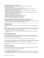
... caused by the improper insertion of a PC Card or the installation of an incompatible card • Improper disc insertion or use of non-ThinkPad products, prototype cards, or modified options can lead to false indications of the program. Note: The diagnostic tests are not covered under warranty:... • Damage caused by spilling a liquid onto the keyboard • Use of an incorrect ac power adapter on the screen. The Lenovo Solution Center program is available for download at http://www.lenovo.com/diags To run the Lenovo Solution Center program, go to Control Panel and click System...
... caused by the improper insertion of a PC Card or the installation of an incompatible card • Improper disc insertion or use of non-ThinkPad products, prototype cards, or modified options can lead to false indications of the program. Note: The diagnostic tests are not covered under warranty:... • Damage caused by spilling a liquid onto the keyboard • Use of an incorrect ac power adapter on the screen. The Lenovo Solution Center program is available for download at http://www.lenovo.com/diags To run the Lenovo Solution Center program, go to Control Panel and click System...
Hardware Maintenance Manual
Page 42
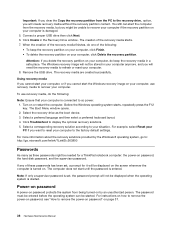
... the recovery media in the Recovery Drive window. Remove the USB drive. Note: If only a supervisor password is set , a prompt for a ThinkPad notebook computer: the power-on password, the hard disk password, and the supervisor password. Power-on password A power-on password protects the system from...Passwords As many as the boot device. 3. Connect a proper USB drive then click Next. 6. Select a preferred language and then select a preferred keyboard layout. 4. For instructions on how to remove the power-on password, see "How to reset your computer is entered. Turn on page 37....
... the recovery media in the Recovery Drive window. Remove the USB drive. Note: If only a supervisor password is set , a prompt for a ThinkPad notebook computer: the power-on password, the hard disk password, and the supervisor password. Power-on password A power-on password protects the system from...Passwords As many as the boot device. 3. Connect a proper USB drive then click Next. 6. Select a preferred language and then select a preferred keyboard layout. 4. For instructions on how to remove the power-on password, see "How to reset your computer is entered. Turn on page 37....

Hardware Maintenance Manual
Page 53
... on the sound, press F1, F2, or F3. Has the same function as the Break key on a conventional keyboard. © Copyright Lenovo 2013 47 Has the same function as the ScrLK key on a conventional keyboard. To input F1-F12, press the function keys directly. Darkens the display. For Windows 8: Opens the Search charm...
... on the sound, press F1, F2, or F3. Has the same function as the Break key on a conventional keyboard. © Copyright Lenovo 2013 47 Has the same function as the ScrLK key on a conventional keyboard. To input F1-F12, press the function keys directly. Darkens the display. For Windows 8: Opens the Search charm...

Hardware Maintenance Manual
Page 57
...are shipped with the replacement CRU; and (2) you can request that are available from Lenovo at http://www.lenovo.com/support. Examples of these types of the replacement CRU. Installation of CRUs: ...the ac power adapter, power cord, battery, and hard disk drive or solid-state drive. ThinkPad computers contain the following types of self-service CRUs is your product with finger print reader ... can find the manual for your product. You might include the memory module, wireless card, keyboard, and palm rest with a replacement part you . Self-service CRUs: These CRUs unplug or...
...are shipped with the replacement CRU; and (2) you can request that are available from Lenovo at http://www.lenovo.com/support. Examples of these types of the replacement CRU. Installation of CRUs: ...the ac power adapter, power cord, battery, and hard disk drive or solid-state drive. ThinkPad computers contain the following types of self-service CRUs is your product with finger print reader ... can find the manual for your product. You might include the memory module, wireless card, keyboard, and palm rest with a replacement part you . Self-service CRUs: These CRUs unplug or...

Hardware Maintenance Manual
Page 59
...and CRUs No. FRU description 1 LCD unit 2 Power button board 3 Keyboard bezel assembly with touch pad (with fingerprint reader on some models) 4 Backup battery 5 Wireless WAN card 5 M.2 solid-state drive 6 Wireless LAN card 7 Battery pack 8 Lenovo OneLink connector cover 9 DC-in bracket and DC-in support bracket 10...with bracket 16 Speaker assembly 17 Base cover assembly 18 Microprocessor 19 Memory module 20 System board assembly 21 Thermal fan assembly 22 Keyboard 23 TrackPoint cap Self-service CRU No No No Yes No No No Yes Yes No No Yes No Yes Yes Yes ...
...and CRUs No. FRU description 1 LCD unit 2 Power button board 3 Keyboard bezel assembly with touch pad (with fingerprint reader on some models) 4 Backup battery 5 Wireless WAN card 5 M.2 solid-state drive 6 Wireless LAN card 7 Battery pack 8 Lenovo OneLink connector cover 9 DC-in bracket and DC-in support bracket 10...with bracket 16 Speaker assembly 17 Base cover assembly 18 Microprocessor 19 Memory module 20 System board assembly 21 Thermal fan assembly 22 Keyboard 23 TrackPoint cap Self-service CRU No No No Yes No No No Yes Yes No No Yes No Yes Yes Yes ...

Hardware Maintenance Manual
Page 83
... part marked a as shown in order: • "1020 Battery pack" on page 65 Chapter 9. You need to imperfect contact with an integrated thermal pipes b a 1120 Keyboard For access, remove these FRUs in the following illustrations.
... part marked a as shown in order: • "1020 Battery pack" on page 65 Chapter 9. You need to imperfect contact with an integrated thermal pipes b a 1120 Keyboard For access, remove these FRUs in the following illustrations.

Hardware Maintenance Manual
Page 84
To reveal the screw heads beneath the keyboard frame, slide the keyboard frame forward by 2.5 mm (0.1 inch) with the keyboard multi-tool. 2 78 Hardware Maintenance Manual Unlock the keyboard frame. 1 2. Removal steps of the keyboard 1. The following illustration shows a keyboard multi-tool. Keyboard multi-tool When you remove the keyboard, use the keyboard multi-tool.
To reveal the screw heads beneath the keyboard frame, slide the keyboard frame forward by 2.5 mm (0.1 inch) with the keyboard multi-tool. 2 78 Hardware Maintenance Manual Unlock the keyboard frame. 1 2. Removal steps of the keyboard 1. The following illustration shows a keyboard multi-tool. Keyboard multi-tool When you remove the keyboard, use the keyboard multi-tool.

Hardware Maintenance Manual
Page 85
3. Removing or replacing a FRU 79 Pivot the keyboard slightly upward until you can see the connectors on the bottom side of the keyboard. Then turn over the keyboard. 5 4 Chapter 9. Loosen the screws that secure the keyboard with the keyboard multi-tool. 3 4.
3. Removing or replacing a FRU 79 Pivot the keyboard slightly upward until you can see the connectors on the bottom side of the keyboard. Then turn over the keyboard. 5 4 Chapter 9. Loosen the screws that secure the keyboard with the keyboard multi-tool. 3 4.

Hardware Maintenance Manual
Page 86
Attach the connectors and then turn over the keyboard. 4 3 2 1 5 80 Hardware Maintenance Manual Then remove the keyboard. 6 7 8 9 Installation steps of the keyboard 1. 5. Gently put the keyboard on the palm rest and detach the connectors.
Attach the connectors and then turn over the keyboard. 4 3 2 1 5 80 Hardware Maintenance Manual Then remove the keyboard. 6 7 8 9 Installation steps of the keyboard 1. 5. Gently put the keyboard on the palm rest and detach the connectors.

Hardware Maintenance Manual
Page 87
Ensure that the screw heads are exposed completely. 7 Chapter 9. Reveal the screw heads by sliding the keyboard frame forward with the keyboard multi-tool. Insert the keyboard into the space under the frame of the keyboard bezel. 6 6 3. Removing or replacing a FRU 81 2.
Ensure that the screw heads are exposed completely. 7 Chapter 9. Reveal the screw heads by sliding the keyboard frame forward with the keyboard multi-tool. Insert the keyboard into the space under the frame of the keyboard bezel. 6 6 3. Removing or replacing a FRU 81 2.

Hardware Maintenance Manual
Page 88
Tighten the screws with your finger as shown. 9 9 82 Hardware Maintenance Manual 4. Hide the latches of the keyboard frame under the keyboard bezel by 2.5 mm (0.1 inch) with the keyboard multi-tool. Slide the keyboard frame backward by pushing the latches with the keyboard multi-tool to secure the keyboard in place. 8 5.
Tighten the screws with your finger as shown. 9 9 82 Hardware Maintenance Manual 4. Hide the latches of the keyboard frame under the keyboard bezel by 2.5 mm (0.1 inch) with the keyboard multi-tool. Slide the keyboard frame backward by pushing the latches with the keyboard multi-tool to secure the keyboard in place. 8 5.

Hardware Maintenance Manual
Page 89
Adjust the keyboard frame in order: • "1020 Battery pack" on page 65 • "1030 Large bottom cover" on page 66 • "1050 Optical drive or blank bezel" on page 68 • "1070 Hard disk drive assembly or solid-state drive assembly" on page 69 • "1120 Keyboard" on page 77 Chapter 9. Removing or replacing a FRU 83 Turn the computer over and lock the keyboard frame. 11 1130 Keyboard bezel For access, remove these FRUs in place with the keyboard multi-tool and ensure that all the latches are secured under the keyboard bezel. 10 7. 6.
Adjust the keyboard frame in order: • "1020 Battery pack" on page 65 • "1030 Large bottom cover" on page 66 • "1050 Optical drive or blank bezel" on page 68 • "1070 Hard disk drive assembly or solid-state drive assembly" on page 69 • "1120 Keyboard" on page 77 Chapter 9. Removing or replacing a FRU 83 Turn the computer over and lock the keyboard frame. 11 1130 Keyboard bezel For access, remove these FRUs in place with the keyboard multi-tool and ensure that all the latches are secured under the keyboard bezel. 10 7. 6.

Hardware Maintenance Manual
Page 90
Removal steps of the keyboard bezel assembly 1 1 2 2 2 1 1 1 1 1 1 1 1 1 1 Step 1 2 Screw (quantity) M2 × 7 mm, wafer-head, nylon-coated (12) M2 × 2.5 mm, wafer-head, nylon-coated (3) Color Black Black Torque 0.181 Nm (1.85 kgf-cm) 0.181 Nm (1.85 kgf-cm) 3 3 3 Step 3 Screw (quantity) M2 × 7 mm, wafer-head, nylon-coated (3) Color Black Torque 0.181 Nm (1.85 kgf-cm) 84 Hardware Maintenance Manual
Removal steps of the keyboard bezel assembly 1 1 2 2 2 1 1 1 1 1 1 1 1 1 1 Step 1 2 Screw (quantity) M2 × 7 mm, wafer-head, nylon-coated (12) M2 × 2.5 mm, wafer-head, nylon-coated (3) Color Black Black Torque 0.181 Nm (1.85 kgf-cm) 0.181 Nm (1.85 kgf-cm) 3 3 3 Step 3 Screw (quantity) M2 × 7 mm, wafer-head, nylon-coated (3) Color Black Torque 0.181 Nm (1.85 kgf-cm) 84 Hardware Maintenance Manual

Hardware Maintenance Manual
Page 92
When you service the microprocessor, avoid any kind of rough handling. 86 Hardware Maintenance Manual In step 11 , release the keyboard bezel from the frame using a plastic pry tool. 11 11 11 11 11 11 11 11 11 11 11 11 1140 Microprocessor For access, remove these FRUs in order: • "1020 Battery pack" on page 65 • "1030 Large bottom cover" on page 66 • "1110 Thermal fan assembly" on page 75 Attention: The microprocessor is extremely sensitive.
When you service the microprocessor, avoid any kind of rough handling. 86 Hardware Maintenance Manual In step 11 , release the keyboard bezel from the frame using a plastic pry tool. 11 11 11 11 11 11 11 11 11 11 11 11 1140 Microprocessor For access, remove these FRUs in order: • "1020 Battery pack" on page 65 • "1030 Large bottom cover" on page 66 • "1110 Thermal fan assembly" on page 75 Attention: The microprocessor is extremely sensitive.

Hardware Maintenance Manual
Page 94
... LAN card" on page 73 • "1100 Backup battery" on page 74 • "1110 Thermal fan assembly" on page 75 • "1120 Keyboard" on page 77 • "1130 Keyboard bezel" on page 83 • "1140 Microprocessor" on page 86 Removal steps of the system board Attention: The following components soldered on the...
... LAN card" on page 73 • "1100 Backup battery" on page 74 • "1110 Thermal fan assembly" on page 75 • "1120 Keyboard" on page 77 • "1130 Keyboard bezel" on page 83 • "1140 Microprocessor" on page 86 Removal steps of the system board Attention: The following components soldered on the...

Hardware Maintenance Manual
Page 96
...; "1050 Optical drive or blank bezel" on page 68 • "1070 Hard disk drive assembly or solid-state drive assembly" on page 69 • "1120 Keyboard" on page 77 • "1130 Keyboard bezel" on page 83 90 Hardware Maintenance Manual
...; "1050 Optical drive or blank bezel" on page 68 • "1070 Hard disk drive assembly or solid-state drive assembly" on page 69 • "1120 Keyboard" on page 77 • "1130 Keyboard bezel" on page 83 90 Hardware Maintenance Manual

Hardware Maintenance Manual
Page 97
... (quantity) M2 × 3.5 mm, wafer-head, nylon-coated (1) Color Black Torque 0.181 Nm (1.85 kgf-cm) 6 4 1170 DC-in bracket, DC-in order: • "1010 Lenovo OneLink connector cover" on page 65 • "1020 Battery pack" on page 65 • "1030 Large bottom cover" on page 66 • "1050 Optical drive... page 68 • "1070 Hard disk drive assembly or solid-state drive assembly" on page 69 • "1100 Backup battery" on page 74 • "1120 Keyboard" on page 77 Chapter 9.
... (quantity) M2 × 3.5 mm, wafer-head, nylon-coated (1) Color Black Torque 0.181 Nm (1.85 kgf-cm) 6 4 1170 DC-in bracket, DC-in order: • "1010 Lenovo OneLink connector cover" on page 65 • "1020 Battery pack" on page 65 • "1030 Large bottom cover" on page 66 • "1050 Optical drive... page 68 • "1070 Hard disk drive assembly or solid-state drive assembly" on page 69 • "1100 Backup battery" on page 74 • "1120 Keyboard" on page 77 Chapter 9.

Hardware Maintenance Manual
Page 98
• "1130 Keyboard bezel" on page 83 Removal steps of the DC-in bracket 1 2 5 Step 1 Screw (quantity) M2 × 3.5 mm, wafer-head, nylon-coated (1) Removal steps of the DC-in connector with RJ45 sub card Color Black Torque 0.181 Nm (1.85 kgf-cm) 1 92 Hardware Maintenance Manual
• "1130 Keyboard bezel" on page 83 Removal steps of the DC-in bracket 1 2 5 Step 1 Screw (quantity) M2 × 3.5 mm, wafer-head, nylon-coated (1) Removal steps of the DC-in connector with RJ45 sub card Color Black Torque 0.181 Nm (1.85 kgf-cm) 1 92 Hardware Maintenance Manual

Hardware Maintenance Manual
Page 100
... LAN card" on page 73 • "1100 Backup battery" on page 74 • "1110 Thermal fan assembly" on page 75 • "1120 Keyboard" on page 77 • "1130 Keyboard bezel" on page 83 • "1150 System board assembly" on page 87 • "1160 Card reader with USB connector sub card" on page...
... LAN card" on page 73 • "1100 Backup battery" on page 74 • "1110 Thermal fan assembly" on page 75 • "1120 Keyboard" on page 77 • "1130 Keyboard bezel" on page 83 • "1150 System board assembly" on page 87 • "1160 Card reader with USB connector sub card" on page...


