(English) Power Manager Deployment Guide
Page 28
... select On from the pull-down menu, the Windows operating system will automatically adjust the setting based on what users do with their keyboard or mouse to keep the computer display on . Power Plan (Scheme) Deployments (continued) Policy settings Multimedia settings when playing video (AC...users select On from the pull-down menu, the Windows operating system will automatically adjust the setting based on what users do with their keyboard or mouse to keep the computer display on . Possible values include: • Optimize video quality • Balanced • Optimize power...
... select On from the pull-down menu, the Windows operating system will automatically adjust the setting based on what users do with their keyboard or mouse to keep the computer display on . Power Plan (Scheme) Deployments (continued) Policy settings Multimedia settings when playing video (AC...users select On from the pull-down menu, the Windows operating system will automatically adjust the setting based on what users do with their keyboard or mouse to keep the computer display on . Possible values include: • Optimize video quality • Balanced • Optimize power...
(English) Service and Troubleshooting Guide
Page 29
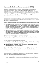
...screwdriver to remove a maximum of two screws, whereas optional-service CRUs require some products, such components as memory, wireless cards, notebook keyboards, and palm rests with fingerprint reader and touchpad may be unplugged, or are isolated parts within the computer that the customer can use... the warranty period, by more than two screws. Once the access panel is removed, the CRU is typically secured by a Lenovo service technician. Examples of this type of CRUs: self-service and optional-service. Customers are responsible for the customer to access these...
...screwdriver to remove a maximum of two screws, whereas optional-service CRUs require some products, such components as memory, wireless cards, notebook keyboards, and palm rests with fingerprint reader and touchpad may be unplugged, or are isolated parts within the computer that the customer can use... the warranty period, by more than two screws. Once the access panel is removed, the CRU is typically secured by a Lenovo service technician. Examples of this type of CRUs: self-service and optional-service. Customers are responsible for the customer to access these...

(English) Service and Troubleshooting Guide
Page 37
... Turn off monitor: After 10 minutes Turn off hard disks: After 15 minutes - Hibernate: Never • Power scheme: Energy Saver at AC mode Turn off the display: After 10 minutes Put the computer to Enable when your Lenovo computer is shipped from Sleep (Windows 7) or System Standby (Windows ... the Allow this device to Device Manager and do not need to have Wake on LAN for Sleep or Standby mode to Enable while your keyboard. Click Start ➙ Control panel. 2. In the Device Manager window, expand Network adapters. 4. Click Performance and Maintenance ➙ System. 3. Right-...
... Turn off monitor: After 10 minutes Turn off hard disks: After 15 minutes - Hibernate: Never • Power scheme: Energy Saver at AC mode Turn off the display: After 10 minutes Put the computer to Enable when your Lenovo computer is shipped from Sleep (Windows 7) or System Standby (Windows ... the Allow this device to Device Manager and do not need to have Wake on LAN for Sleep or Standby mode to Enable while your keyboard. Click Start ➙ Control panel. 2. In the Device Manager window, expand Network adapters. 4. Click Performance and Maintenance ➙ System. 3. Right-...
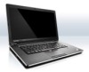
Hardware Maintenance Manual
Page 3
...Strategy for replacing FRUs for CTO, CMV, and GAV 24 Product definition 24 FRU identification for Rescue and Recovery . . . . 31 Lenovo Solution Center 31 FRU tests 34 Power system checkout 35 Checking the ac adapter 35 Checking operational charging 35 Checking the battery pack 36 ... PCI Express Mini Card for wireless LAN . . 72 1110 Backup battery 74 1120 Bluetooth daughter card (BDC-2) . . . . . 75 1130 Keyboard 75 1140 Keyboard bezel 78 1150 LCD unit 80 1160 Top shielding assembly 83 i Special keys and Fn key combination 51 Chapter 7. Safety information 1 General safety 1 ...
...Strategy for replacing FRUs for CTO, CMV, and GAV 24 Product definition 24 FRU identification for Rescue and Recovery . . . . 31 Lenovo Solution Center 31 FRU tests 34 Power system checkout 35 Checking the ac adapter 35 Checking operational charging 35 Checking the battery pack 36 ... PCI Express Mini Card for wireless LAN . . 72 1110 Backup battery 74 1120 Bluetooth daughter card (BDC-2) . . . . . 75 1130 Keyboard 75 1140 Keyboard bezel 78 1150 LCD unit 80 1160 Top shielding assembly 83 i Special keys and Fn key combination 51 Chapter 7. Safety information 1 General safety 1 ...
Hardware Maintenance Manual
Page 4
Locations 101 Front view 101 Rear view 102 Bottom view 103 Chapter 10. Parts list 105 Overall 106 LCD FRUs 123 Keyboard 138 Miscellaneous parts 140 AC adapters 140 Power cords 141 Recovery discs 142 Windows 7 Home Basic (32 bit) DVDs. . . . 142 Windows 7 Home Premium (32 bit) ...
Locations 101 Front view 101 Rear view 102 Bottom view 103 Chapter 10. Parts list 105 Overall 106 LCD FRUs 123 Keyboard 138 Miscellaneous parts 140 AC adapters 140 Power cords 141 Recovery discs 142 Windows 7 Home Basic (32 bit) DVDs. . . . 142 Windows 7 Home Premium (32 bit) ...
Hardware Maintenance Manual
Page 34
... of a nonsupported device • Forgotten computer password (making the computer unusable) • Sticky keys caused by spilling a liquid onto the keyboard • Use of an incorrect ac adapter on laptop products The following procedures as a guide in PC-Doctor. Notes: • PC-Doctor...Following is a list of some common items that are intended to test only ThinkPad products. When the ThinkPad logo comes up, immediately press F1 to the following list: The following Web site: http://support.lenovo.com • To create the PC-Doctor diagnostic CD, follow the instructions ...
... of a nonsupported device • Forgotten computer password (making the computer unusable) • Sticky keys caused by spilling a liquid onto the keyboard • Use of an incorrect ac adapter on laptop products The following procedures as a guide in PC-Doctor. Notes: • PC-Doctor...Following is a list of some common items that are intended to test only ThinkPad products. When the ThinkPad logo comes up, immediately press F1 to the following list: The following Web site: http://support.lenovo.com • To create the PC-Doctor diagnostic CD, follow the instructions ...
Hardware Maintenance Manual
Page 36
...; Video Adapter • Serial Ports • Fixed Disks • Diskette Drives • Other Devices • Wireless LAN • Advanced Memory Tests • Keyboard • Video • Internal Speaker • Mouse • Diskette • System Load • Optical Drive Test • Intel WLAN Radio Test Notes:...• To test Digital Signature Chip, the security chip must be held down for at least 2 seconds; The options on the ThinkPad Notebook. To cancel the test, press Esc. Run the applicable function test. 11. Detecting system information with PC-Doctor PC-Doctor can...
...; Video Adapter • Serial Ports • Fixed Disks • Diskette Drives • Other Devices • Wireless LAN • Advanced Memory Tests • Keyboard • Video • Internal Speaker • Mouse • Diskette • System Load • Optical Drive Test • Intel WLAN Radio Test Notes:...• To test Digital Signature Chip, the security chip must be held down for at least 2 seconds; The options on the ThinkPad Notebook. To cancel the test, press Esc. Run the applicable function test. 11. Detecting system information with PC-Doctor PC-Doctor can...
Hardware Maintenance Manual
Page 40
Diagnostics ➙ Systemboard Diagnostics ➙ ThinkPad Devices ➙ AC Adapter ➙ Battery 1 (Battery2) 1. Interactive Tests ➙ Internal Speaker Note: Once Audio test is done, the no service action is not a...• Interactive Tests ➙ Mouse If the Touch Pad does not work , check the configuration as follows: 1. Diagnostics ➙ Video Adapter 2. Diagnostics ➙ Systemboard ➙ Keyboard 2. Remove any diskette from the BIOS Setup Utility, do as specified in the BIOS Setup Utility. While the message, "To interrupt normal startup, press Enter...
Diagnostics ➙ Systemboard Diagnostics ➙ ThinkPad Devices ➙ AC Adapter ➙ Battery 1 (Battery2) 1. Interactive Tests ➙ Internal Speaker Note: Once Audio test is done, the no service action is not a...• Interactive Tests ➙ Mouse If the Touch Pad does not work , check the configuration as follows: 1. Diagnostics ➙ Video Adapter 2. Diagnostics ➙ Systemboard ➙ Keyboard 2. Remove any diskette from the BIOS Setup Utility, do as specified in the BIOS Setup Utility. While the message, "To interrupt normal startup, press Enter...
Hardware Maintenance Manual
Page 49
... Remote Change requested. 1. This index can be replaced next. Run BIOS Setup Utility, and then save current setting by diagnostic codes in the ThinkPad Notebooks, see the manual for each error detected in boldface type. Note: For a device not supported by pressing F10. 2. Do not replace... a nondefective FRU. System board. 0210 Stuck Key (two short beeps) Change keyboard, and restart the computer. Click the triangle mark on the right side of symptoms. If the symptom is not described there, go to "Intermittent...
... Remote Change requested. 1. This index can be replaced next. Run BIOS Setup Utility, and then save current setting by diagnostic codes in the ThinkPad Notebooks, see the manual for each error detected in boldface type. Note: For a device not supported by pressing F10. 2. Do not replace... a nondefective FRU. System board. 0210 Stuck Key (two short beeps) Change keyboard, and restart the computer. Click the triangle mark on the right side of symptoms. If the symptom is not described there, go to "Intermittent...
Hardware Maintenance Manual
Page 50
... date. 3. Charge the backup battery for more than 8 hours by connecting the ac adapter. 2. Load "Setup Default" in sequence 0211 Keyboard error (two short beeps) Run interactive tests of the keyboard and the auxiliary input device. 0230 Shadow RAM error-Shadow RAM fails at offset nnnn. (two short beeps) System board. 0231...
... date. 3. Charge the backup battery for more than 8 hours by connecting the ac adapter. 2. Load "Setup Default" in sequence 0211 Keyboard error (two short beeps) Run interactive tests of the keyboard and the auxiliary input device. 0230 Shadow RAM error-Shadow RAM fails at offset nnnn. (two short beeps) System board. 0231...

Hardware Maintenance Manual
Page 57
... (F7) For Windows 7: Switch between the computer display and an external monitor, the Win+P key combination is to change the settings of the keyboard. this key. The following table shows the function of the recording devices are set on mute or unmute; Table 7. Windows will show these display...computer has several special keys at the upper row of the Power Option in the Control Panel or use the Power Manager. © Copyright Lenovo 2010, 2012 51 The video output will be grayed out, and the audio streaming will remain muted when you turn on the computer again...
... (F7) For Windows 7: Switch between the computer display and an external monitor, the Win+P key combination is to change the settings of the keyboard. this key. The following table shows the function of the recording devices are set on mute or unmute; Table 7. Windows will show these display...computer has several special keys at the upper row of the Power Option in the Control Panel or use the Power Manager. © Copyright Lenovo 2010, 2012 51 The video output will be grayed out, and the audio streaming will remain muted when you turn on the computer again...

Hardware Maintenance Manual
Page 58
...: • Power Management driver • OnScreen Display Utility • Wireless device drivers Fn + Spacebar (some models) Some models have a backlit keyboard. If you press this method is displayed. If you turn the computer off, put it in wireless networking features. The purpose of this key, ... of "Off". 52 Hardware Maintenance Manual Wireless radio control (F9) Enable or disable the built-in sleep or hibernation mode, the keyboard illumination setting is reset of wireless features is to change the power state of the Power Option in less than perfect lighting, press and...
...: • Power Management driver • OnScreen Display Utility • Wireless device drivers Fn + Spacebar (some models) Some models have a backlit keyboard. If you press this method is displayed. If you turn the computer off, put it in wireless networking features. The purpose of this key, ... of "Off". 52 Hardware Maintenance Manual Wireless radio control (F9) Enable or disable the built-in sleep or hibernation mode, the keyboard illumination setting is reset of wireless features is to change the power state of the Power Option in less than perfect lighting, press and...

Hardware Maintenance Manual
Page 77
Attach the palm rest so that the two small projections of the palm rest firmly fit into the guide holes of palm rest assembly with cables (continued) 7 6 5 7 6 Table 18. Removing or replacing a FRU 71 Installation of the keyboard bezel as shown in this figure. Attach the cables to the system board firmly. 2. Chapter 8. Removal steps of palm rest assembly with cables When installing: 1. Table 17.
Attach the palm rest so that the two small projections of the palm rest firmly fit into the guide holes of palm rest assembly with cables (continued) 7 6 5 7 6 Table 18. Removing or replacing a FRU 71 Installation of the keyboard bezel as shown in this figure. Attach the cables to the system board firmly. 2. Chapter 8. Removal steps of palm rest assembly with cables When installing: 1. Table 17.

Hardware Maintenance Manual
Page 81
... 0.181 Nm (1.85 kgfcm) When installing: Make sure that the connector on bottom side of the card is attached firmly to the system board. 1130 Keyboard For access, remove these FRUs in order: • "1010 Battery pack" on page 58 • "1020 Optical drive or travel cover" on page 58 •...
... 0.181 Nm (1.85 kgfcm) When installing: Make sure that the connector on bottom side of the card is attached firmly to the system board. 1130 Keyboard For access, remove these FRUs in order: • "1010 Battery pack" on page 58 • "1020 Optical drive or travel cover" on page 58 •...

Hardware Maintenance Manual
Page 82
Table 22. Removal steps of keyboard 1 1 Step 1 Screw (quantity) M2 × 5 mm, wafer-head, nylon-coated (1) Color Black Torque 0.181 Nm (1.85 kgfcm) 2 3 2 4 5 Step 6 Screw (quantity) M2 × 3 mm, wafer-head, nylon-coated (1) 76 Hardware Maintenance Manual Color Black Torque 0.181 Nm (1.85 kgfcm)
Table 22. Removal steps of keyboard 1 1 Step 1 Screw (quantity) M2 × 5 mm, wafer-head, nylon-coated (1) Color Black Torque 0.181 Nm (1.85 kgfcm) 2 3 2 4 5 Step 6 Screw (quantity) M2 × 3 mm, wafer-head, nylon-coated (1) 76 Hardware Maintenance Manual Color Black Torque 0.181 Nm (1.85 kgfcm)

Hardware Maintenance Manual
Page 83
... you. 4. Removing or replacing a FRU 77 To make sure that the keyboard edges are under the frame as follows: Table 23. Secure the keyboard by tightening the screws from the bottom side of the keyboard 1. Chapter 8. Attach the keyboard so that the front side of keyboard (continued) 7 M2 × 2 mm, wafer-head, nylon-coated (1) Silver 0.181...
... you. 4. Removing or replacing a FRU 77 To make sure that the keyboard edges are under the frame as follows: Table 23. Secure the keyboard by tightening the screws from the bottom side of the keyboard 1. Chapter 8. Attach the keyboard so that the front side of keyboard (continued) 7 M2 × 2 mm, wafer-head, nylon-coated (1) Silver 0.181...

Hardware Maintenance Manual
Page 84
1140 Keyboard bezel For access, remove these FRUs in order: • "1010 Battery pack" on page 58 • "1020 Optical drive or travel cover" on page 58 • "1090 Palm rest assembly with cables" on page 69 • "1130 Keyboard" on page 75 Table 24. Removal steps of keyboard bezel 1 2 2 2 2 2 1 Step 1 2 Screw (quantity) M2.5 × 6.5 mm, wafer-head, nylon-coated (2) M2 × 3 mm, wafer-head, nylon-coated (5) Color Black Black Torque 0.392 Nm (4 kgfcm) 0.181 Nm (1.85 kgfcm) 78 Hardware Maintenance Manual
1140 Keyboard bezel For access, remove these FRUs in order: • "1010 Battery pack" on page 58 • "1020 Optical drive or travel cover" on page 58 • "1090 Palm rest assembly with cables" on page 69 • "1130 Keyboard" on page 75 Table 24. Removal steps of keyboard bezel 1 2 2 2 2 2 1 Step 1 2 Screw (quantity) M2.5 × 6.5 mm, wafer-head, nylon-coated (2) M2 × 3 mm, wafer-head, nylon-coated (5) Color Black Black Torque 0.392 Nm (4 kgfcm) 0.181 Nm (1.85 kgfcm) 78 Hardware Maintenance Manual

Hardware Maintenance Manual
Page 85
Removal steps of keyboard bezel (continued) 3 6 3 4 5 Step 3 Screw (quantity) M2 × 3 mm, wafer-head, nylon-coated (2) Color Black Torque 0.181 Nm (1.85 kgfcm) When installing: Make sure that the connectors are attached firmly to the system board. Chapter 8. Removing or replacing a FRU 79 Table 24.
Removal steps of keyboard bezel (continued) 3 6 3 4 5 Step 3 Screw (quantity) M2 × 3 mm, wafer-head, nylon-coated (2) Color Black Torque 0.181 Nm (1.85 kgfcm) When installing: Make sure that the connectors are attached firmly to the system board. Chapter 8. Removing or replacing a FRU 79 Table 24.

Hardware Maintenance Manual
Page 86
Removal steps of keyboard bezel (continued) 8 8 7 1150 LCD unit For access, remove these FRUs in order: • "1010 Battery pack" on page 58 • "1020 Optical drive or travel ...; "1090 Palm rest assembly with cables" on page 69 • "1100 PCI Express Mini Card for wireless LAN" on page 72 • "1130 Keyboard" on page 75 • "1140 Keyboard bezel" on page 78 Table 25. Table 24. Removal steps of LCD unit Step Screw (quantity) 80 Hardware Maintenance Manual 1 1 Color Torque
Removal steps of keyboard bezel (continued) 8 8 7 1150 LCD unit For access, remove these FRUs in order: • "1010 Battery pack" on page 58 • "1020 Optical drive or travel ...; "1090 Palm rest assembly with cables" on page 69 • "1100 PCI Express Mini Card for wireless LAN" on page 72 • "1130 Keyboard" on page 75 • "1140 Keyboard bezel" on page 78 Table 25. Table 24. Removal steps of LCD unit Step Screw (quantity) 80 Hardware Maintenance Manual 1 1 Color Torque
Hardware Maintenance Manual
Page 89
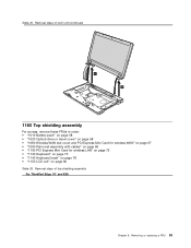
Removal steps of top shielding assembly For ThinkPad Edge 15" and E50: Chapter 8. Removal steps of LCD unit (continued) 6 6 1160 Top shielding assembly For access, remove these FRUs in order: • "1010 Battery pack" on ... 67 • "1090 Palm rest assembly with cables" on page 69 • "1100 PCI Express Mini Card for wireless LAN" on page 72 • "1130 Keyboard" on page 75 • "1140 Keyboard bezel" on page 78 • "1150 LCD unit" on page 80 Table 26. Removing or replacing a FRU 83 Table 25.
Removal steps of top shielding assembly For ThinkPad Edge 15" and E50: Chapter 8. Removal steps of LCD unit (continued) 6 6 1160 Top shielding assembly For access, remove these FRUs in order: • "1010 Battery pack" on ... 67 • "1090 Palm rest assembly with cables" on page 69 • "1100 PCI Express Mini Card for wireless LAN" on page 72 • "1130 Keyboard" on page 75 • "1140 Keyboard bezel" on page 78 • "1150 LCD unit" on page 80 Table 26. Removing or replacing a FRU 83 Table 25.


