Hardware Maintenance Manual
Page 3
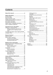
... Passwords 24 Power-on password 24 Supervisor password 24 Power management 25 Screen blank mode 25 Sleep (standby) mode 25 Hibernation mode 26 Lenovo G470/G475/G570/G575 27 Specifications 27 Status indicators 29 Fn key combinations 31 FRU replacement notices 32 Screw notices 32 Removing and replacing an ...DIMM 40 1070 Fan assembly and Heat Sink assembly 41 1080 CPU 44 1090 PCI Express Mini Card for wireless LAN 45 1100 Keyboard 47 1110 Keyboard bezel 49 1120 Power board and touch inductive panel 52 1130 System board 53 1140 LCD unit 56 1150 Speakers, bluetooth daughter card...
... Passwords 24 Power-on password 24 Supervisor password 24 Power management 25 Screen blank mode 25 Sleep (standby) mode 25 Hibernation mode 26 Lenovo G470/G475/G570/G575 27 Specifications 27 Status indicators 29 Fn key combinations 31 FRU replacement notices 32 Screw notices 32 Removing and replacing an ...DIMM 40 1070 Fan assembly and Heat Sink assembly 41 1080 CPU 44 1090 PCI Express Mini Card for wireless LAN 45 1100 Keyboard 47 1110 Keyboard bezel 49 1120 Power board and touch inductive panel 52 1130 System board 53 1140 LCD unit 56 1150 Speakers, bluetooth daughter card...
Hardware Maintenance Manual
Page 24
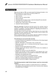
... device •• Forgotten computer password (making the computer unusable) •• Sticky keys caused by spilling a liquid onto the keyboard •• Use of an incorrect AC adapter on the diskette drive cover, foreign material in the parts exchange form or parts return...laptop products The following information in the drive, or the insertion of a diskette with the computer, determine whether the damage is a list of some symptoms that might indicate that have been subjected to excessive force, or dropped. 20 Failing FRU name and part number 7. Lenovo G470...
... device •• Forgotten computer password (making the computer unusable) •• Sticky keys caused by spilling a liquid onto the keyboard •• Use of an incorrect AC adapter on the diskette drive cover, foreign material in the parts exchange form or parts return...laptop products The following information in the drive, or the insertion of a diskette with the computer, determine whether the damage is a list of some symptoms that might indicate that have been subjected to excessive force, or dropped. 20 Failing FRU name and part number 7. Lenovo G470...

Hardware Maintenance Manual
Page 29
... Note: Power management modes are not supported for APM operating system. To end screen blank mode and resume normal operation, press any operation with the keyboard, the hard disk, the parallel connector, or the diskette drive within that time. •• If the battery indicator is amber, indicating that the battery...
... Note: Power management modes are not supported for APM operating system. To end screen blank mode and resume normal operation, press any operation with the keyboard, the hard disk, the parallel connector, or the diskette drive within that time. •• If the battery indicator is amber, indicating that the battery...

Hardware Maintenance Manual
Page 30
...hibernation mode, perform that action: - When the power is turned on the timer, and if the user does not do any operation with the keyboard, the hard disk drive, the parallel connector, or the diskette drive within that causes the system to enter hibernation mode, follow the steps below.... •• If the timer conditions are satisfied in the boot record on the hard disk. •• The system is powered off. Lenovo G470/G475/G570/G575 Hardware Maintenance Manual Hibernation mode In hibernation mode, the following occurs: •• The system status, RAM, VRAM, and setup ...
...hibernation mode, perform that action: - When the power is turned on the timer, and if the user does not do any operation with the keyboard, the hard disk drive, the parallel connector, or the diskette drive within that causes the system to enter hibernation mode, follow the steps below.... •• If the timer conditions are satisfied in the boot record on the hard disk. •• The system is powered off. Lenovo G470/G475/G570/G575 Hardware Maintenance Manual Hibernation mode In hibernation mode, the following occurs: •• The system status, RAM, VRAM, and setup ...
Hardware Maintenance Manual
Page 32
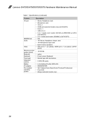
...Lenovo G470/G475/G570/G575 Hardware Maintenance Manual Table 1. Specifications (continued) Feature I/O port MODEM slot Audio Video Ethernet (on the system board) Bluetooth Keyboard Touch pad Integrated camera Battery AC adapter Pre-installed operating system Description • Stereo Headphone Jack • Microphone Jack • VGA x 1 • HDMI port (selected models only) (G470...8226; CRT port x 1 (on planar), HDMI port x 1 (on planar) (G470/ G570) • 10/100 Mb • option • 6-row Lenovo Keyboard • Normal type with two buttons • 0.3M/2.0M pixels • Li-ion...
...Lenovo G470/G475/G570/G575 Hardware Maintenance Manual Table 1. Specifications (continued) Feature I/O port MODEM slot Audio Video Ethernet (on the system board) Bluetooth Keyboard Touch pad Integrated camera Battery AC adapter Pre-installed operating system Description • Stereo Headphone Jack • Microphone Jack • VGA x 1 • HDMI port (selected models only) (G470...8226; CRT port x 1 (on planar), HDMI port x 1 (on planar) (G470/ G570) • 10/100 Mb • option • 6-row Lenovo Keyboard • Normal type with two buttons • 0.3M/2.0M pixels • Li-ion...

Hardware Maintenance Manual
Page 33
... in uppercase without pressing the Shift key. Status indicators Indicator 1 Caps lock 2 Num lock 3 Power on the keyboard is in hibernate mode or shut down. 29 You can enter all alphabetic characters (A-Z) in sleep mode. Lenovo G470/G475/G570/G575 Status indicators The system status indicators below show the computer status: 12 3 4 5 6 Table...
... in uppercase without pressing the Shift key. Status indicators Indicator 1 Caps lock 2 Num lock 3 Power on the keyboard is in hibernate mode or shut down. 29 You can enter all alphabetic characters (A-Z) in sleep mode. Lenovo G470/G475/G570/G575 Status indicators The system status indicators below show the computer status: 12 3 4 5 6 Table...

Hardware Maintenance Manual
Page 51
Removal steps of keyboard Remove the screws 1, 2 on page 37 Figure 10. Lenovo G470/G475/G570/G575 1100 Keyboard For access, remove these FRUs in order: •• "1010 Battery pack" on page 34 •• "1040 Hard disk drive (HDD)/Memory/CPU (Central processing unit)/Mini PCI ExpressCard slot compartment cover " on the bottom. 1 1 2 Step 1 2 Screw (quantity) M2.5 × 8 mm, flat-head, nylon-coated (2) M2.5 × 4 mm, flat-head, nylon-coated (1) Color Black Black Torque 2.0kgfcm 2.0kgfcm 47
Removal steps of keyboard Remove the screws 1, 2 on page 37 Figure 10. Lenovo G470/G475/G570/G575 1100 Keyboard For access, remove these FRUs in order: •• "1010 Battery pack" on page 34 •• "1040 Hard disk drive (HDD)/Memory/CPU (Central processing unit)/Mini PCI ExpressCard slot compartment cover " on the bottom. 1 1 2 Step 1 2 Screw (quantity) M2.5 × 8 mm, flat-head, nylon-coated (2) M2.5 × 4 mm, flat-head, nylon-coated (1) Color Black Black Torque 2.0kgfcm 2.0kgfcm 47

Hardware Maintenance Manual
Page 52
Removal steps of keyboard (continued) Lift the keyboard a little 3, unlock the FPC connector and then detach the connector in the direction shown by arrows 4 5. 3 4 5 When installing: Make sure that the FPC connector is attached firmly and then lock the FPC connector. 48 Lenovo G470/G475/G570/G575 Hardware Maintenance Manual Figure 10.
Removal steps of keyboard (continued) Lift the keyboard a little 3, unlock the FPC connector and then detach the connector in the direction shown by arrows 4 5. 3 4 5 When installing: Make sure that the FPC connector is attached firmly and then lock the FPC connector. 48 Lenovo G470/G475/G570/G575 Hardware Maintenance Manual Figure 10.
Hardware Maintenance Manual
Page 53
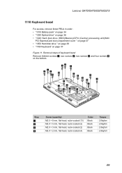
... Remove thirteen screws 1, two screws 2, two screws 3 and four screws 4 on page 47 Figure 11. Lenovo G470/G475/G570/G575 1110 Keyboard bezel For access, remove these FRUs in order: •• "1010 Battery pack" on page 34 •• .../CPU (Central processing unit)/Mini PCI ExpressCard slot compartment cover " on page 37 •• "1050 Hard disk drive " on page 38 •• "1100 Keyboard" on the bottom. 11 1 1 1 1 3 3 1 4 4 1 4 1 4 1 1 2 2 1 1 Step 1 2 3 4 Screw (quantity) M2.5 × 8 mm, flat-head, nylon-coated (13) M2.0 × 5 mm, flat-head,...
... Remove thirteen screws 1, two screws 2, two screws 3 and four screws 4 on page 47 Figure 11. Lenovo G470/G475/G570/G575 1110 Keyboard bezel For access, remove these FRUs in order: •• "1010 Battery pack" on page 34 •• .../CPU (Central processing unit)/Mini PCI ExpressCard slot compartment cover " on page 37 •• "1050 Hard disk drive " on page 38 •• "1100 Keyboard" on the bottom. 11 1 1 1 1 3 3 1 4 4 1 4 1 4 1 1 2 2 1 1 Step 1 2 3 4 Screw (quantity) M2.5 × 8 mm, flat-head, nylon-coated (13) M2.0 × 5 mm, flat-head,...

Hardware Maintenance Manual
Page 54
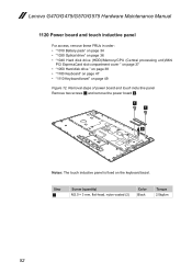
Lenovo G470/G475/G570/G575 Hardware Maintenance Manual Figure 11. Removal steps of keyboard bezel (continued) Remove one screw 5 and detach three FPC connectors in the direction shown by arrows 6. 6 5 6 Step 5 Screw (quantity) M2.5 × 8 mm, flat-head, nylon-coated (1) Color Black Torque 2.0kgfcm When installing: Make sure that all the FPC connectors are attached firmly. 50
Lenovo G470/G475/G570/G575 Hardware Maintenance Manual Figure 11. Removal steps of keyboard bezel (continued) Remove one screw 5 and detach three FPC connectors in the direction shown by arrows 6. 6 5 6 Step 5 Screw (quantity) M2.5 × 8 mm, flat-head, nylon-coated (1) Color Black Torque 2.0kgfcm When installing: Make sure that all the FPC connectors are attached firmly. 50

Hardware Maintenance Manual
Page 55
Removal steps of keyboard bezel (continued) Remove the keyboard bezel in the direction shown by arrows 7. 7 51 Lenovo G470/G475/G570/G575 Figure 11.
Removal steps of keyboard bezel (continued) Remove the keyboard bezel in the direction shown by arrows 7. 7 51 Lenovo G470/G475/G570/G575 Figure 11.
Hardware Maintenance Manual
Page 56
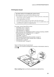
... touch inductive panel is fixed on page 49 Figure 12. Step 1 Screw (quantity) M2.0 × 3 mm, flat-head, nylon-coated (2) Color Black Torque 2.0kgfcm 52 Lenovo G470/G475/G570/G575 Hardware Maintenance Manual 1120 Power board and touch inductive panel For access, remove these FRUs in order: •• "1010 Battery pack.../CPU (Central processing unit)/Mini PCI ExpressCard slot compartment cover " on page 37 •• "1050 Hard disk drive " on page 38 •• "1100 Keyboard" on page 47 •• "1110...
... touch inductive panel is fixed on page 49 Figure 12. Step 1 Screw (quantity) M2.0 × 3 mm, flat-head, nylon-coated (2) Color Black Torque 2.0kgfcm 52 Lenovo G470/G475/G570/G575 Hardware Maintenance Manual 1120 Power board and touch inductive panel For access, remove these FRUs in order: •• "1010 Battery pack.../CPU (Central processing unit)/Mini PCI ExpressCard slot compartment cover " on page 37 •• "1050 Hard disk drive " on page 38 •• "1100 Keyboard" on page 47 •• "1110...
Hardware Maintenance Manual
Page 57
Lenovo G470/G475/G570/G575 1130 System board Important notices for wireless LAN" on page 45 •• "1100 Keyboard" on page 47 •• "1110 Keyboard bezel" on a bench top that the connectors are attached firmly. 53 For access, remove these FRUs in the direction shown by arrows 1. 1 1 When installing: Make ...
Lenovo G470/G475/G570/G575 1130 System board Important notices for wireless LAN" on page 45 •• "1100 Keyboard" on page 47 •• "1110 Keyboard bezel" on a bench top that the connectors are attached firmly. 53 For access, remove these FRUs in the direction shown by arrows 1. 1 1 When installing: Make ...
Hardware Maintenance Manual
Page 60
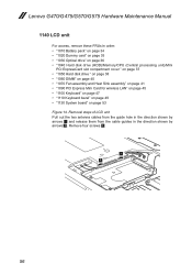
Remove four screws 3. 1 1 56 Removal steps of LCD unit Pull out the two antenna cables from the guide hole in the direction shown by arrows 2. Lenovo G470/G475/G570/G575 Hardware Maintenance Manual 1140 LCD unit For access, remove these FRUs in the direction shown by arrows 1 and release them from the ... Fan assembly and Heat Sink assembly" on page 41 •• "1090 PCI Express Mini Card for wireless LAN" on page 45 •• "1100 Keyboard" on page 47 •• "1110 Keyboard bezel" on page 49 •• "1130 System board" on page 53 Figure 14.
Remove four screws 3. 1 1 56 Removal steps of LCD unit Pull out the two antenna cables from the guide hole in the direction shown by arrows 2. Lenovo G470/G475/G570/G575 Hardware Maintenance Manual 1140 LCD unit For access, remove these FRUs in the direction shown by arrows 1 and release them from the ... Fan assembly and Heat Sink assembly" on page 41 •• "1090 PCI Express Mini Card for wireless LAN" on page 45 •• "1100 Keyboard" on page 47 •• "1110 Keyboard bezel" on page 49 •• "1130 System board" on page 53 Figure 14.
Hardware Maintenance Manual
Page 63
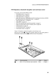
...;• "1090 PCI Express Mini Card for wireless LAN" on page 45 •• "1100 Keyboard" on page 47 •• "1110 Keyboard bezel" on page 49 •• "1130 System board" on page 53 Figure 15. Lenovo G470/G475/G570/G575 1150 Speakers, bluetooth daughter card and base cover For access, remove these...
...;• "1090 PCI Express Mini Card for wireless LAN" on page 45 •• "1100 Keyboard" on page 47 •• "1110 Keyboard bezel" on page 49 •• "1130 System board" on page 53 Figure 15. Lenovo G470/G475/G570/G575 1150 Speakers, bluetooth daughter card and base cover For access, remove these...
Hardware Maintenance Manual
Page 68
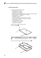
... Mini Card for wireless LAN" on page 45 •• "1100 Keyboard" on page 47 •• "1110 Keyboard bezel" on page 49 •• "1130 System board" on page 53 •• "1140 LCD unit" on page 56 Figure 16. Lenovo G470/G475/G570/G575 Hardware Maintenance Manual 1160 LCD front bezel For...
... Mini Card for wireless LAN" on page 45 •• "1100 Keyboard" on page 47 •• "1110 Keyboard bezel" on page 49 •• "1130 System board" on page 53 •• "1140 LCD unit" on page 56 Figure 16. Lenovo G470/G475/G570/G575 Hardware Maintenance Manual 1160 LCD front bezel For...
Hardware Maintenance Manual
Page 69
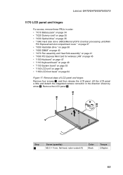
..." on page 45 •• "1100 Keyboard" on page 47 •• "1110 Keyboard bezel" on page 49 •• "1130 System board" on page 53 •• "1140 LCD unit" on page 56 •• "1160 LCD front bezel" on page 64 Figure 17. Lenovo G470/G475/G570/G575 1170 LCD panel and...
..." on page 45 •• "1100 Keyboard" on page 47 •• "1110 Keyboard bezel" on page 49 •• "1130 System board" on page 53 •• "1140 LCD unit" on page 56 •• "1160 LCD front bezel" on page 64 Figure 17. Lenovo G470/G475/G570/G575 1170 LCD panel and...
Hardware Maintenance Manual
Page 71
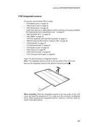
Lenovo G470/G475/G570/G575 1180 Integrated camera For access, remove these FRUs in the figure above. 67 When replacing the integrated camera, route the connector cable ... Heat Sink assembly" on page 41 •• "1090 PCI Express Mini Card for wireless LAN" on page 45 •• "1100 Keyboard" on page 47 •• "1110 Keyboard bezel" on page 49 •• "1130 System board" on page 53 •• "1140 LCD unit" on page 56 ••...
Lenovo G470/G475/G570/G575 1180 Integrated camera For access, remove these FRUs in the figure above. 67 When replacing the integrated camera, route the connector cable ... Heat Sink assembly" on page 41 •• "1090 PCI Express Mini Card for wireless LAN" on page 45 •• "1100 Keyboard" on page 47 •• "1110 Keyboard bezel" on page 49 •• "1130 System board" on page 53 •• "1140 LCD unit" on page 56 ••...
Hardware Maintenance Manual
Page 72
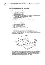
... Heat Sink assembly" on page 41 •• "1090 PCI Express Mini Card for wireless LAN" on page 45 •• "1100 Keyboard" on page 47 •• "1110 Keyboard bezel" on page 49 •• "1130 System board" on page 53 •• "1140 LCD unit" on page 56 ••... tapes. Tension could cause the cables to any tension. As you route the cables, make sure that they are not subjected to be broken. 68 Lenovo G470/G475/G570/G575 Hardware Maintenance Manual 1190 Antenna assembly and LCD cover For access, remove these FRUs in the direction shown by the cable guides...
... Heat Sink assembly" on page 41 •• "1090 PCI Express Mini Card for wireless LAN" on page 45 •• "1100 Keyboard" on page 47 •• "1110 Keyboard bezel" on page 49 •• "1130 System board" on page 53 •• "1140 LCD unit" on page 56 ••... tapes. Tension could cause the cables to any tension. As you route the cables, make sure that they are not subjected to be broken. 68 Lenovo G470/G475/G570/G575 Hardware Maintenance Manual 1190 Antenna assembly and LCD cover For access, remove these FRUs in the direction shown by the cable guides...

Hardware Maintenance Manual
Page 75
Lenovo G470/G475/G570/G575 Parts list This section presents the following service parts: •• "Overall" on page 72 •• "LCD FRUs" on page 77 •• "Keyboard" on page 79 •• "Miscellaneous parts" on page 84 •• "AC adapters" on page 85 •• "Power cords" on page 86 Notes: • Each FRU is available for all types or models, unless specific types or models are specified. 71
Lenovo G470/G475/G570/G575 Parts list This section presents the following service parts: •• "Overall" on page 72 •• "LCD FRUs" on page 77 •• "Keyboard" on page 79 •• "Miscellaneous parts" on page 84 •• "AC adapters" on page 85 •• "Power cords" on page 86 Notes: • Each FRU is available for all types or models, unless specific types or models are specified. 71


