
Owners Manual
Page 2
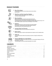
How to Use the Washer ... 14 Maintenance ... 17 Troubleshooting Guide 20 Warranty 23 Built-in Heater Internal heater helps to maintain water temperature at its optimum level for selected cycles I Child Lock The Child ...
How to Use the Washer ... 14 Maintenance ... 17 Troubleshooting Guide 20 Warranty 23 Built-in Heater Internal heater helps to maintain water temperature at its optimum level for selected cycles I Child Lock The Child ...
Owners Manual
Page 20
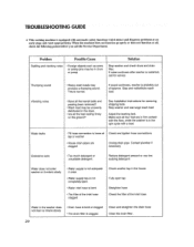
TROUBLESHOOTING GUIDE * This washing machine is not adequate in the spin cycle with a load Water leaks Fii[ hose connection [s loose at tap or washer . When tile ...
TROUBLESHOOTING GUIDE * This washing machine is not adequate in the spin cycle with a load Water leaks Fii[ hose connection [s loose at tap or washer . When tile ...
Owners Manual
Page 21
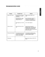
... shut Close the door and press the Start/Pause button After pressing the Start/Pause button, it corrected by the amount of RLM & PLC modem. TROUBLESHOOTING GUIDE : Problem Washer does not start Poss_le Cause • Electrical power cord may not be plugged in or connection may vary by a qualified electrician - N 21...
... shut Close the door and press the Start/Pause button After pressing the Start/Pause button, it corrected by the amount of RLM & PLC modem. TROUBLESHOOTING GUIDE : Problem Washer does not start Poss_le Cause • Electrical power cord may not be plugged in or connection may vary by a qualified electrician - N 21...
Owners Manual
Page 22
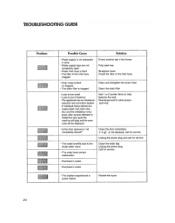
... Unplug the power plug Call for service • Overload in motor • Overload in motor • The washer experienced a power failure Restart the cycle 22 TROUBLESHOOTING GUIDE Problem Possible Cause Solution -
... Unplug the power plug Call for service • Overload in motor • Overload in motor • The washer experienced a power failure Restart the cycle 22 TROUBLESHOOTING GUIDE Problem Possible Cause Solution -
Service Manual
Page 3
TROUBLESHOOTING...17 7-1. BEFORE PERFORMING SERVICE 17 7-2. ERROR DIAGNOSIS AND CHECK LIST 20 8-1. DISASSEMBLY INSTRUCTIONS 32 10. CABINET & CONTROL PANEL ASSEMBLY 41 10-2. DRUM & TUB ASSEMBLY 42 ... ...3 2. DISPENSER ASSEMBLY 43 2 FEATURES & TECHNICAL EXPLANATION 4 3. HOW TO CHECK THE WATER LEVEL FREQUENCY 17 7-4. EXPLODED VIEW ...41 10-1. QC TEST MODE...17 7-3. FAULT DIAGNOSIS AND TROUBLESHOOTING 23 9. WIRING DIAGRAM/PROGRAM CHART 14 7.
TROUBLESHOOTING...17 7-1. BEFORE PERFORMING SERVICE 17 7-2. ERROR DIAGNOSIS AND CHECK LIST 20 8-1. DISASSEMBLY INSTRUCTIONS 32 10. CABINET & CONTROL PANEL ASSEMBLY 41 10-2. DRUM & TUB ASSEMBLY 42 ... ...3 2. DISPENSER ASSEMBLY 43 2 FEATURES & TECHNICAL EXPLANATION 4 3. HOW TO CHECK THE WATER LEVEL FREQUENCY 17 7-4. EXPLODED VIEW ...41 10-1. QC TEST MODE...17 7-3. FAULT DIAGNOSIS AND TROUBLESHOOTING 23 9. WIRING DIAGRAM/PROGRAM CHART 14 7.

Service Manual
Page 9
... The appliance should be installed as follows: REMOVE THE SHIPPING BOLTS INSTALL THE APPLIANCE ON A FLAT AND FIRM SURFACE Remove the 4 shipping bolts with the troubleshooting guide. Turn clockwise to lower. 8 counterclockwise to raise; Check the setup (power supply is . INSTALLATION & TEST Before servicing, ask the customer what the trouble is...
... The appliance should be installed as follows: REMOVE THE SHIPPING BOLTS INSTALL THE APPLIANCE ON A FLAT AND FIRM SURFACE Remove the 4 shipping bolts with the troubleshooting guide. Turn clockwise to lower. 8 counterclockwise to raise; Check the setup (power supply is . INSTALLATION & TEST Before servicing, ask the customer what the trouble is...

Service Manual
Page 18
... . 7-2. HOW TO CHECK THE WATER LEVEL FREQUENCY Press the SPIN SPEED and SOIL LEVEL button simultaneously. The voltage of electric shock when disconnecting parts while troubleshooting. Press the Start/Pause button repeatedly to cycle through the test modes. Number of 241 x.1 kHz = 24.1 kHz 17 So, for 3 sec. 10 times Circulation... the off and unlock the door. The digits indicate the water level frequency ( x.1 kHz ). QC TEST MODE. Press the Power button, while the above condition. TROUBLESHOOTING 7-1. Press the SPIN SPEED and SOIL LEVEL buttons simultaneously. 2.
... . 7-2. HOW TO CHECK THE WATER LEVEL FREQUENCY Press the SPIN SPEED and SOIL LEVEL button simultaneously. The voltage of electric shock when disconnecting parts while troubleshooting. Press the Start/Pause button repeatedly to cycle through the test modes. Number of 241 x.1 kHz = 24.1 kHz 17 So, for 3 sec. 10 times Circulation... the off and unlock the door. The digits indicate the water level frequency ( x.1 kHz ). QC TEST MODE. Press the Power button, while the above condition. TROUBLESHOOTING 7-1. Press the SPIN SPEED and SOIL LEVEL buttons simultaneously. 2.
Service Manual
Page 24
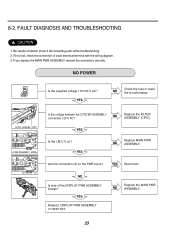
FAULT DIAGNOSIS AND TROUBLESHOOTING CAUTION 1. NO POWER Connector Is the supplied voltage 110/120 V AC? YES Replace DISPLAY PWB ASSEMBLY or repair wire. 8-2. Be careful of each electrical terminal .... YES Reconnect. YES NO Check the fuse or reset the circuit breaker. First of all, check the connection of electric shock if disconnecting parts while troubleshooting. 2. Replace the FILTER ASSEMBLY (CIRC). Are the connectors (2) on ? NO Is wire of the DISPLAY PWB ASSEMBLY broken? NO Replace the MAIN PWB ASSEMBLY. 23...
FAULT DIAGNOSIS AND TROUBLESHOOTING CAUTION 1. NO POWER Connector Is the supplied voltage 110/120 V AC? YES Replace DISPLAY PWB ASSEMBLY or repair wire. 8-2. Be careful of each electrical terminal .... YES Reconnect. YES NO Check the fuse or reset the circuit breaker. First of all, check the connection of electric shock if disconnecting parts while troubleshooting. 2. Replace the FILTER ASSEMBLY (CIRC). Are the connectors (2) on ? NO Is wire of the DISPLAY PWB ASSEMBLY broken? NO Replace the MAIN PWB ASSEMBLY. 23...

