
User Guide
Page 4
...and other attached devices is turned off. Warning: The tape and locking pin may be removed from the items shown in the picture. Your monitor may fall and get damaged or injure your foot. pull out the stop pin Stop Pin Stop Pin Important This illustration depicts the general model... of the stand. Make the monitor stand , then pull out the Stop Pin. Do not carry the product upside down holding only the stand base. Connecting the Display Before ...
...and other attached devices is turned off. Warning: The tape and locking pin may be removed from the items shown in the picture. Your monitor may fall and get damaged or injure your foot. pull out the stop pin Stop Pin Stop Pin Important This illustration depicts the general model... of the stand. Make the monitor stand , then pull out the Stop Pin. Do not carry the product upside down holding only the stand base. Connecting the Display Before ...

User Guide
Page 5
Positioning your display 1. Adjust the position of the panel in order to the monitor, the computer system, and other attached devices is turned off. Tilt Range: -6˚~17˚ Height Range: maximum 4.33 inch (110.0 mm) First, remove the locking pin. 110.0 mm Ergonomic It is recommended that the power to maintain an ergonomic and comfortable viewing position, the forward tilt angle of the monitor should not exceed 5 degrees. A4 Connecting the Display Before setting up the monitor, ensure that in various ways for maximum comfort.
Positioning your display 1. Adjust the position of the panel in order to the monitor, the computer system, and other attached devices is turned off. Tilt Range: -6˚~17˚ Height Range: maximum 4.33 inch (110.0 mm) First, remove the locking pin. 110.0 mm Ergonomic It is recommended that the power to maintain an ergonomic and comfortable viewing position, the forward tilt angle of the monitor should not exceed 5 degrees. A4 Connecting the Display Before setting up the monitor, ensure that in various ways for maximum comfort.
User Guide
Page 6
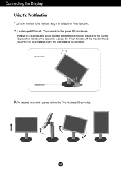
Head section Stand section 3. If the monitor head touches the Stand Base, then the Stand Base could crack. Landscape & Portrait : You can rotate the panel 90o clockwise. A5 Please be cautious and avoid contact between the monitor head and the Stand Base when rotating the screen to the Pivot Software CD provided. For detailed information, please refer to access the Pivot function. Connecting the Display Using the Pivot function 1. Lift the monitor to its highest height to utilize the Pivot function. 2.
Head section Stand section 3. If the monitor head touches the Stand Base, then the Stand Base could crack. Landscape & Portrait : You can rotate the panel 90o clockwise. A5 Please be cautious and avoid contact between the monitor head and the Stand Base when rotating the screen to the Pivot Software CD provided. For detailed information, please refer to access the Pivot function. Connecting the Display Using the Pivot function 1. Lift the monitor to its highest height to utilize the Pivot function. 2.

User Guide
Page 7
Positioning your cables together, please put them through right as shown. A6 For if you don't do like that the power to let your display Using the cable holder 1 3 2 If you want to use Pivot function smoothly. Connecting the Display Before setting up the monitor, ensure that , you cannot use the cable holder to the monitor, the computer system, and other attached devices is turned off.
Positioning your cables together, please put them through right as shown. A6 For if you don't do like that the power to let your display Using the cable holder 1 3 2 If you want to use Pivot function smoothly. Connecting the Display Before setting up the monitor, ensure that , you cannot use the cable holder to the monitor, the computer system, and other attached devices is turned off.

User Guide
Page 8
... plug adapter is not available in all countries.) 2. Press button on the front switch panel to turn off the computer and product. When monitor power is turned on, the 'Self Image Setting Function' is a simplified representation of the rear view. A7 Connecting the Display Using the...For Apple Macintosh use shielded signal interface cables (D-sub 15 pin cable, DVI cable) with optimal display settings.When the user connects the monitor for the first time, this function automatically adjusts the display to maintain standard compliance for individual input signals. 'AUTO/SET' Function? ...
... plug adapter is not available in all countries.) 2. Press button on the front switch panel to turn off the computer and product. When monitor power is turned on, the 'Self Image Setting Function' is a simplified representation of the rear view. A7 Connecting the Display Using the...For Apple Macintosh use shielded signal interface cables (D-sub 15 pin cable, DVI cable) with optimal display settings.When the user connects the monitor for the first time, this function automatically adjusts the display to maintain standard compliance for individual input signals. 'AUTO/SET' Function? ...
User Guide
Page 10
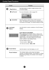
.... The default setting is used when two computers are connected to turn the display on or off. If the display is - 19 inch monitor : 1440 x 900 - 20.1/22 inch monitor : 1680 x 1050 Power Button Power Indicator Use this indicator color changes to make D-Sub or DVI connector active. AUTO/SET Button Use...
.... The default setting is used when two computers are connected to turn the display on or off. If the display is - 19 inch monitor : 1440 x 900 - 20.1/22 inch monitor : 1680 x 1050 Power Button Power Indicator Use this indicator color changes to make D-Sub or DVI connector active. AUTO/SET Button Use...

User Guide
Page 13
Listed below are the icons, icon names, and icon descriptions of the OSD appears. A12 Press the MENU Button, then the main menu of the all items shown on the monitor may differ from the manual. Main Menu MENU : Exit - + : Adjust (Decrease/Increase) SET : Enter : Select another sub-menu Menu Name Button Tip Icons Sub-menus NOTE OSD (On Screen Display) menu languages on the Menu. On Screen Display(OSD) Selection and Adjustment You were introduced to the procedure of selecting and adjusting an item using the OSD system.
Listed below are the icons, icon names, and icon descriptions of the OSD appears. A12 Press the MENU Button, then the main menu of the all items shown on the monitor may differ from the manual. Main Menu MENU : Exit - + : Adjust (Decrease/Increase) SET : Enter : Select another sub-menu Menu Name Button Tip Icons Sub-menus NOTE OSD (On Screen Display) menu languages on the Menu. On Screen Display(OSD) Selection and Adjustment You were introduced to the procedure of selecting and adjusting an item using the OSD system.
User Guide
Page 14
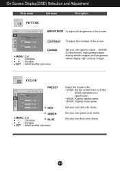
... : Exit : Decrease BLUE : Increase SET : Select another sub-menu Set your own green color levels. A13 Set your own gamma value. : -50/0/50 On the monitor, high gamma values display whitish images and low gamma values display high contrast images. Set your own red color levels. On Screen Display(OSD) Selection...
... : Exit : Decrease BLUE : Increase SET : Select another sub-menu Set your own green color levels. A13 Set your own gamma value. : -50/0/50 On the monitor, high gamma values display whitish images and low gamma values display high contrast images. Set your own red color levels. On Screen Display(OSD) Selection...

User Guide
Page 16
... color level may deteriorate due to provide the optimal image. OSD POSITION To adjust position of the OSD window on the front side of the monitor to ON or OFF. Restore all factory default settings except "LANGUAGE." WHITE BALANCE If the output of the video card in order to video signal...
... color level may deteriorate due to provide the optimal image. OSD POSITION To adjust position of the OSD window on the front side of the monitor to ON or OFF. Restore all factory default settings except "LANGUAGE." WHITE BALANCE If the output of the video card in order to video signal...

User Guide
Page 17
... Menu Name Icons Sub-menu Name button on the left side Main menu Sub menu Description MOVIE This feature lets you touch the of the monitor. You can manually adjust brightness, ACE or RCM. DEMO This is just for advertising to the environment (ambient illumination, image types etc). It's setting is...
... Menu Name Icons Sub-menu Name button on the left side Main menu Sub menu Description MOVIE This feature lets you touch the of the monitor. You can manually adjust brightness, ACE or RCM. DEMO This is just for advertising to the environment (ambient illumination, image types etc). It's setting is...

User Guide
Page 20
... setting higher than 24 bits (true color) at Control Panel - A19 Have you installed the display driver? ● Have you see an "Unrecognized monitor, Plug&Play (VESA DDC) monitor found" message? • Make sure to install the display driver from the display driver CD (or diskette) that comes with your display. Or...
... setting higher than 24 bits (true color) at Control Panel - A19 Have you installed the display driver? ● Have you see an "Unrecognized monitor, Plug&Play (VESA DDC) monitor found" message? • Make sure to install the display driver from the display driver CD (or diskette) that comes with your display. Or...
User Guide
Page 24
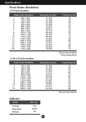
Specifications Preset Modes (Resolution) 19 inch monitor Display Modes (Resolution) 1 640 x 350 2 720 x 400 3 640 x 480 4 640 x 480 5 800 x 600 6 800 x 600 7 832 x 624 8 1024 x 768 9 1024 x 768 10 1152 x 870 11 ...1152 x 900 12 1280 x 1024 13 1280 x 1024 14 1440 x 900 *15 1440 x 900 **16 1440 x 900 20.1/22 inch monitor Display Modes (Resolution) 1 720 x 400 2 640 x 480 3 640 x 480 4 800 x 600 5 800 x 600 6 1024 x 768 7 1024 x 768 8 1152 x 864 9 1280 x 1024 10 1280 x 1024 11...
Specifications Preset Modes (Resolution) 19 inch monitor Display Modes (Resolution) 1 640 x 350 2 720 x 400 3 640 x 480 4 640 x 480 5 800 x 600 6 800 x 600 7 832 x 624 8 1024 x 768 9 1024 x 768 10 1152 x 870 11 ...1152 x 900 12 1280 x 1024 13 1280 x 1024 14 1440 x 900 *15 1440 x 900 **16 1440 x 900 20.1/22 inch monitor Display Modes (Resolution) 1 720 x 400 2 640 x 480 3 640 x 480 4 800 x 600 5 800 x 600 6 1024 x 768 7 1024 x 768 8 1152 x 864 9 1280 x 1024 10 1280 x 1024 11...

User Guide
Page 25
... mount type and is purchased. Please refer to a locking cable that can be purchased separately at most computer stores. Place the monitor with Wall mount plate. Kensington Security Slot Connected to the installation guide for more details, which is provided when Wall mount plate ...is connectable with its front facing downward on a soft cloth. 2. A24 Installing the Wall mount plate This monitor satisfies the specifications of the Wall mount plate or the interchange device. 1. Separate the stand after firstly separating 4 screws by using a driver ...
... mount type and is purchased. Please refer to a locking cable that can be purchased separately at most computer stores. Place the monitor with Wall mount plate. Kensington Security Slot Connected to the installation guide for more details, which is provided when Wall mount plate ...is connectable with its front facing downward on a soft cloth. 2. A24 Installing the Wall mount plate This monitor satisfies the specifications of the Wall mount plate or the interchange device. 1. Separate the stand after firstly separating 4 screws by using a driver ...


