

Service Manual
Page 7
Position/ V-Position 3) Tracking : Clock/Phase 4) Auto Configure 5) Reset 1: Y 3: Pb 5: Pr 7: Line1 Ready 9: LINE2 11: LINE3 13: Line3 Ready Unit Remark DVI-I input Middle east /NTSC Only D4 Jack (525i,525p,750p,1125i) 5 Power ON Stand by DPMS Mode Power off 6 LCD Module 2: Y GND 4: Pb GND 6: Pr ...
Position/ V-Position 3) Tracking : Clock/Phase 4) Auto Configure 5) Reset 1: Y 3: Pb 5: Pr 7: Line1 Ready 9: LINE2 11: LINE3 13: Line3 Ready Unit Remark DVI-I input Middle east /NTSC Only D4 Jack (525i,525p,750p,1125i) 5 Power ON Stand by DPMS Mode Power off 6 LCD Module 2: Y GND 4: Pb GND 6: Pr ...

Service Manual
Page 8
...,I,LL' BG,DK BG,I,LL' X X O X O O X X X Pr+/-, vol+/-, ok, menu, tv/av, power Top(option) PAL/NTSC Rear(RT/RM) Side Side, Rear(RT/RM) Rear(RZ) Rear(RZ) DVI D-Sub 9 pin(RM) (RM) Stereo -8-
...,I,LL' BG,DK BG,I,LL' X X O X O O X X X Pr+/-, vol+/-, ok, menu, tv/av, power Top(option) PAL/NTSC Rear(RT/RM) Side Side, Rear(RT/RM) Rear(RZ) Rear(RZ) DVI D-Sub 9 pin(RM) (RM) Stereo -8-

Service Manual
Page 11
... 1) Heat Run after converting press IN-START Key and VOL+ Key consequtively from Auto gain menu. 5) fter adjustment is for the application to DVI Jack.. 5) Input digital signal and check pc video in the screen. 6) After appearing the pc video, write digital EDID data. 2.2.1 EDID DATA... 2.1 PC Auto Gain/Offset adjustment 2.1.1 Adjustment preparation 1) Heat Run after 30 minutes execution of white pattern 2) Pattern generator is connected to the DVI Jack of LCD TV. 3) To use Pattern Generator(801GF, VG819) the resolution is XGA(1024 X 768), this pattern gives 16gradation grey scale or...
... 1) Heat Run after converting press IN-START Key and VOL+ Key consequtively from Auto gain menu. 5) fter adjustment is for the application to DVI Jack.. 5) Input digital signal and check pc video in the screen. 6) After appearing the pc video, write digital EDID data. 2.2.1 EDID DATA... 2.1 PC Auto Gain/Offset adjustment 2.1.1 Adjustment preparation 1) Heat Run after 30 minutes execution of white pattern 2) Pattern generator is connected to the DVI Jack of LCD TV. 3) To use Pattern Generator(801GF, VG819) the resolution is XGA(1024 X 768), this pattern gives 16gradation grey scale or...

Service Manual
Page 21
- 21 - DVI PC_R,G,B PAL _ IF SCART1_V SCART2_V SC_R,G,B,FB SIDE_COMP SIDE_Y,C SCART1_L,R SIDE_ L,R SCART2_ L,R PC_ LR (IC200) LA7222C DVI 8 PC_R,G,B 3 M52758 S/W (IC850) R,G,B 3 R,G,B 3 R,G,B SM5301 3 (IC800) VCT49xyI VCTI (IC1) R R,G,B MST9883 8 3 ADC G 8 (IC600) B 8 L MPS7720 R AMP (IC100,IC101) FLI2300 (IC500) RAM (IC501) VOUT_1,2 GM5221 SCALER (IC901) LVDS or TTL OUT ROM (IC900) BLOCK DIAGRAM
- 21 - DVI PC_R,G,B PAL _ IF SCART1_V SCART2_V SC_R,G,B,FB SIDE_COMP SIDE_Y,C SCART1_L,R SIDE_ L,R SCART2_ L,R PC_ LR (IC200) LA7222C DVI 8 PC_R,G,B 3 M52758 S/W (IC850) R,G,B 3 R,G,B 3 R,G,B SM5301 3 (IC800) VCT49xyI VCTI (IC1) R R,G,B MST9883 8 3 ADC G 8 (IC600) B 8 L MPS7720 R AMP (IC100,IC101) FLI2300 (IC500) RAM (IC501) VOUT_1,2 GM5221 SCALER (IC901) LVDS or TTL OUT ROM (IC900) BLOCK DIAGRAM
Service Manual
Page 22
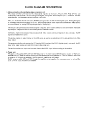
... VCTI, scaler, FLI2300 and AD9883. - 22 - The graphic controller unit receives the PC (analog RGB) input and the DVI-D (digital signal), and sends the PC input to the scaler analog port and DVI-D input to 3.3V and 1.8V through the microcomputer (VCTI) combined with the video decoder that processes both video signals...
... VCTI, scaler, FLI2300 and AD9883. - 22 - The graphic controller unit receives the PC (analog RGB) input and the DVI-D (digital signal), and sends the PC input to the scaler analog port and DVI-D input to 3.3V and 1.8V through the microcomputer (VCTI) combined with the video decoder that processes both video signals...

Service Manual
Page 9
... 78.75 79.50 84.75 84.75 86.375 74.375 VESA(XGA) VESA(XGA) VESA(XGA) VESA(WXGA) VESA(WXGA) Supported HDCP DVI Digital 1080i HDCP DVI Digital 720p VESA VESA VESA VESA Proposed Analog RGB, Digital RGB 9. AV Mode Mid (5 - 8V) - RGB Low (0 - 0.4V) - Wide Screen Low (0 - 2V) - Composite...
... 78.75 79.50 84.75 84.75 86.375 74.375 VESA(XGA) VESA(XGA) VESA(XGA) VESA(WXGA) VESA(WXGA) Supported HDCP DVI Digital 1080i HDCP DVI Digital 720p VESA VESA VESA VESA Proposed Analog RGB, Digital RGB 9. AV Mode Mid (5 - 8V) - RGB Low (0 - 0.4V) - Wide Screen Low (0 - 2V) - Composite...

Service Manual
Page 11
Never connect HDMI & DVI-D & DVI-A Cable at LG TV Plant 00 10 20 30 40 50 60 70 00 02... 00 20 9C 01 48 1E 00 00 01 25 01 88 30 52 FD e - 11 - Product ID Model name RZ-37LZ55 RT-37LZ55 Product ID 30045(A) 30046(A) 30051(A) 30052(D) 30053(A) 30054D) Product ID Dec 30045(A) 30046(D) 30051(A) 30052(D)...Table 5D75 5E75 6375 6475 6575 6675 3. EDID * Caution - Application Range This spec. Model Name(Hex) : Model Name RZ-37LZ55 RT-37LZ55 RM-37LZ55 Model Name(HEX) 525A2D33374C5A3535 52542D33374C5A3535 524D2D33374C5A3535 e. However, the use an isolation transformer. Serial No : ...
Never connect HDMI & DVI-D & DVI-A Cable at LG TV Plant 00 10 20 30 40 50 60 70 00 02... 00 20 9C 01 48 1E 00 00 01 25 01 88 30 52 FD e - 11 - Product ID Model name RZ-37LZ55 RT-37LZ55 Product ID 30045(A) 30046(A) 30051(A) 30052(D) 30053(A) 30054D) Product ID Dec 30045(A) 30046(D) 30051(A) 30052(D)...Table 5D75 5E75 6375 6475 6575 6675 3. EDID * Caution - Application Range This spec. Model Name(Hex) : Model Name RZ-37LZ55 RT-37LZ55 RM-37LZ55 Model Name(HEX) 525A2D33374C5A3535 52542D33374C5A3535 524D2D33374C5A3535 e. However, the use an isolation transformer. Serial No : ...

Service Manual
Page 12
...is completed. 4.2 Adjustment of Auto RGB Color Balance 1) Input the PC 1024x768@75Hz 1/2 Black & White Pattern(MSPG-925F model:39, pattern:18) into Component. (RZ : component , RT/RM : component 1 or 2) 2) Set the PSM to Standard mode in Picture menu. 3) Press the ADJ key on R/C for adjustment. 4)...-Balance, change input mode - B-Offset - 12 - ADC Calibration 4.1 Adjustment of RGB * Required Equipments - Move to AV3(RZ) or AV(RT) or VIDEO(RM) by using D-sub to DVI-I cable) 2) Set the PSM to operate the set , then it becomes automatically. 5) Auto-RGB OK means the adjustment is...
...is completed. 4.2 Adjustment of Auto RGB Color Balance 1) Input the PC 1024x768@75Hz 1/2 Black & White Pattern(MSPG-925F model:39, pattern:18) into Component. (RZ : component , RT/RM : component 1 or 2) 2) Set the PSM to Standard mode in Picture menu. 3) Press the ADJ key on R/C for adjustment. 4)...-Balance, change input mode - B-Offset - 12 - ADC Calibration 4.1 Adjustment of RGB * Required Equipments - Move to AV3(RZ) or AV(RT) or VIDEO(RM) by using D-sub to DVI-I cable) 2) Set the PSM to operate the set , then it becomes automatically. 5) Auto-RGB OK means the adjustment is...