Owner's Manual
Page 2
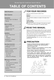
...-0000 to locate the nearest ASC. • This air conditioner is not intended for warranty issues. Just a little preventive care on your part can find the numbers on a label on how to use by young children or invalids without supervision. • Young children should be supervised...they do not play with the air conditioner. • If the power cord requires replacement, have an Authorized Servicer install an exact replacement part. • Installation work must be performed in accordance with the National Electric Code by qualified and authorized personnel only. 2 Room Air ...
...-0000 to locate the nearest ASC. • This air conditioner is not intended for warranty issues. Just a little preventive care on your part can find the numbers on a label on how to use by young children or invalids without supervision. • Young children should be supervised...they do not play with the air conditioner. • If the power cord requires replacement, have an Authorized Servicer install an exact replacement part. • Installation work must be performed in accordance with the National Electric Code by qualified and authorized personnel only. 2 Room Air ...
Owner's Manual
Page 5
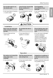
... age or wear. • If the outer case is damaged, it will cause failure of appliance or accident. ENGLISH • Installation Never touch the metal parts of the unit when removing the filter. • They are sharp and may cause failure of machine • It is running. Leaving it out. •... for a long period. • Prevent accidental startup and the possibility of the window, creating a safety hazard. • Operation Be cautious not to run into electric parts.
... age or wear. • If the outer case is damaged, it will cause failure of appliance or accident. ENGLISH • Installation Never touch the metal parts of the unit when removing the filter. • They are sharp and may cause failure of machine • It is running. Leaving it out. •... for a long period. • Prevent accidental startup and the possibility of the window, creating a safety hazard. • Operation Be cautious not to run into electric parts.
Owner's Manual
Page 7
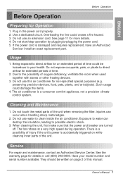
... circuit. Do not use this manual. Usage 1. The air conditioner is damaged and requires replacement, have an Authorized Servicer install an exact replacement part. Do not use water to possible electric shock. 3. Service For repair and maintenance, contact an Authorized Service Center. If the power cord is...properly. 2. Do not start/stop operation by plugging/unplugging the power cord. 5. Do not touch the metal parts of time could be written on while cleaning inner parts of this air conditioner for more details. 4. When cleaning the unit, first make sure that the power and...
... circuit. Do not use this manual. Usage 1. The air conditioner is damaged and requires replacement, have an Authorized Servicer install an exact replacement part. Do not use water to possible electric shock. 3. Service For repair and maintenance, contact an Authorized Service Center. If the power cord is...properly. 2. Do not start/stop operation by plugging/unplugging the power cord. 5. Do not touch the metal parts of time could be written on while cleaning inner parts of this air conditioner for more details. 4. When cleaning the unit, first make sure that the power and...
Service Manual
Page 2
... THE BEST LOCATION ...12 3.2 HOW TO INSTALL ...12 3.3 ELECTRICAL DATA ...15 4. CONTENTS 1. DISASSEMBLY INSTRUCTIONS 5 2.1 MECHANICAL PARTS ...5 2.1.1 FRONT GRILLE ...5 2.1.2 CABINET...5 2.1.3 CONTROL BOARD ...5 2.2 AIR HANDLING PARTS ...6 2.2.1 AIR GUIDE UPPER ...6 2.2.2 ORIFICE, TURBO FAN AND FAN ...6 2.2.3 MOTOR ...7 2.2.4 AIR GUIDE ...7 2.3 ELECTRICAL PARTS ...7 2.3.1 OVERLOAD PROTECTOR ...7 2.3.2 COMPRESSOR ...8 2.3.3 CAPACITOR ...8 2.3.4 THERMOSTAT ...8 2.3.5 ROTARY SWITCH ...8 2.3.6 POWER CORD ...9 2.4 REFRIGERANT CYCLE ...9 2.4.1 CONDENSER ...9 2.4.2 EVAPORATOR ...10 2.4.3 CAPILLARY...
... THE BEST LOCATION ...12 3.2 HOW TO INSTALL ...12 3.3 ELECTRICAL DATA ...15 4. CONTENTS 1. DISASSEMBLY INSTRUCTIONS 5 2.1 MECHANICAL PARTS ...5 2.1.1 FRONT GRILLE ...5 2.1.2 CABINET...5 2.1.3 CONTROL BOARD ...5 2.2 AIR HANDLING PARTS ...6 2.2.1 AIR GUIDE UPPER ...6 2.2.2 ORIFICE, TURBO FAN AND FAN ...6 2.2.3 MOTOR ...7 2.2.4 AIR GUIDE ...7 2.3 ELECTRICAL PARTS ...7 2.3.1 OVERLOAD PROTECTOR ...7 2.3.2 COMPRESSOR ...8 2.3.3 CAPACITOR ...8 2.3.4 THERMOSTAT ...8 2.3.5 ROTARY SWITCH ...8 2.3.6 POWER CORD ...9 2.4 REFRIGERANT CYCLE ...9 2.4.1 CONDENSER ...9 2.4.2 EVAPORATOR ...10 2.4.3 CAPILLARY...
Service Manual
Page 3
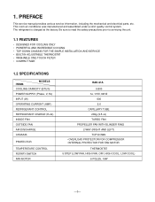
... COOL, LOW COOL) 6 POLES, 16W -3- The refrigerant is charged at the factory. PREFACE This service manual provides various service information, including the mechanical and electrical parts, etc. 1. This room air conditioner was manufactured and assembled under a strict quality control system.
... COOL, LOW COOL) 6 POLES, 16W -3- The refrigerant is charged at the factory. PREFACE This service manual provides various service information, including the mechanical and electrical parts, etc. 1. This room air conditioner was manufactured and assembled under a strict quality control system.
Service Manual
Page 4
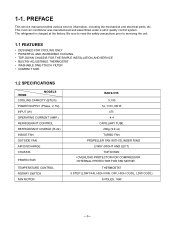
... COOL, LOW COOL) 6 POLES, 16W -3- The refrigerant is charged at the factory. PREFACE This service manual provides various service information, including the mechanical and electrical parts, etc. 1-1.
... COOL, LOW COOL) 6 POLES, 16W -3- The refrigerant is charged at the factory. PREFACE This service manual provides various service information, including the mechanical and electrical parts, etc. 1-1.
Service Manual
Page 5
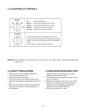
...with an ohm meter between 2 pins (black and white). 2. Unplug the power cord and connect a jumper between the jumpered lead and each exposed metallic part on the equipment at least 3 minutes before switching it back to be over 1 MΩ. -4- The grounding conductor (green or green and yellow) ... power cord. 2. Observe the original lead dress. High Cool - Turn the knob so that arrow points to Off or Fan, wait at all parts which have been overheated or damaged by the short circuit. 3. When servicing, set the ROTARY SWITCH to shock hazards. 1.5 INSULATION RESISTANCE TEST 1. ...
...with an ohm meter between 2 pins (black and white). 2. Unplug the power cord and connect a jumper between the jumpered lead and each exposed metallic part on the equipment at least 3 minutes before switching it back to be over 1 MΩ. -4- The grounding conductor (green or green and yellow) ... power cord. 2. Observe the original lead dress. High Cool - Turn the knob so that arrow points to Off or Fan, wait at all parts which have been overheated or damaged by the short circuit. 3. When servicing, set the ROTARY SWITCH to shock hazards. 1.5 INSULATION RESISTANCE TEST 1. ...

Service Manual
Page 6
... 3 Figure 4 Figure 5 -5- Remove the cabinet. (Refer to control board. (See Figure 1) 3. Using a screwdriver, remove the screw that secure the cabinet to section 2.1.1) 3. DISASSEMBLY INSTRUCTIONS 2.1 MECHANICAL PARTS 2.1.1 FRONT GRILLE 1. Replace the grille by referring to wiring diagram on page 8 for servicing. NOTE : Controls, wires, and capacitor are now accessible for procedures. 6. Disconnect...
... 3 Figure 4 Figure 5 -5- Remove the cabinet. (Refer to control board. (See Figure 1) 3. Using a screwdriver, remove the screw that secure the cabinet to section 2.1.1) 3. DISASSEMBLY INSTRUCTIONS 2.1 MECHANICAL PARTS 2.1.1 FRONT GRILLE 1. Replace the grille by referring to wiring diagram on page 8 for servicing. NOTE : Controls, wires, and capacitor are now accessible for procedures. 6. Disconnect...
Service Manual
Page 7
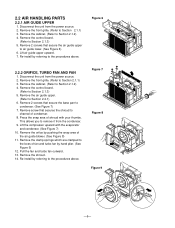
2.2 AIR HANDLING PARTS 2.2.1 AIR GUIDE UPPER 1. Re-install by referring to channel of shroud with the evaporator and condenser. (See Figure 7) 10. Figure 6 2.2.2 ORIFICE, TURBO FAN AND FAN 1. ...
2.2 AIR HANDLING PARTS 2.2.1 AIR GUIDE UPPER 1. Re-install by referring to channel of shroud with the evaporator and condenser. (See Figure 7) 10. Figure 6 2.2.2 ORIFICE, TURBO FAN AND FAN 1. ...
Service Manual
Page 8
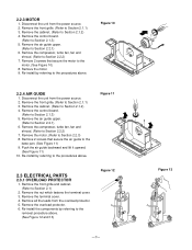
Push the air guide backward and lift it upward. (See Figure 11) 10. Figure 11 2.3 ELECTRICAL PARTS 2.3.1 OVERLOAD PROTECTOR 1. Remove the front grille and cabinet. (Refer to Section 2.1.3) 5. Remove the terminal cover. 4. Re-install the components by referring to the removal procedure ...
Push the air guide backward and lift it upward. (See Figure 11) 10. Figure 11 2.3 ELECTRICAL PARTS 2.3.1 OVERLOAD PROTECTOR 1. Remove the front grille and cabinet. (Refer to Section 2.1.3) 5. Remove the terminal cover. 4. Re-install the components by referring to the removal procedure ...
Service Manual
Page 13
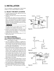
.... INSIDE COOLED AIR OUTSIDE AWNING FENCE HEAT RADIATION 30"-60" Figure 22 ABOUT / 1 4 " Over 20" 3.2 HOW TO INSTALL 3.2.1 WINDOW REQUIREMENTS INNER SILL NOTE: All supporting parts should be no obstacles, such as first strip) in a window. 3.1 SELECT THE BEST LOCATION 1.
.... INSIDE COOLED AIR OUTSIDE AWNING FENCE HEAT RADIATION 30"-60" Figure 22 ABOUT / 1 4 " Over 20" 3.2 HOW TO INSTALL 3.2.1 WINDOW REQUIREMENTS INNER SILL NOTE: All supporting parts should be no obstacles, such as first strip) in a window. 3.1 SELECT THE BEST LOCATION 1.
Service Manual
Page 22
.... Check the terminals. Check the system for the area to be cooled. Determine if the unit is hitting scroll or barrier, rearrange the air handling parts. Remove the cabinet and carefully rearrange the tubing not to cycle. Replace if required. If the condenser fins are closed over a large area on overload...
.... Check the terminals. Check the system for the area to be cooled. Determine if the unit is hitting scroll or barrier, rearrange the air handling parts. Remove the cabinet and carefully rearrange the tubing not to cycle. Replace if required. If the condenser fins are closed over a large area on overload...
Service Manual
Page 23
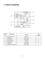
... BL MOTOR 2 7 8 OR(BR) YL CAPACITOR YL F OR(BR) C 6 R BK BK 3 COMP. DESCRIPTION 1 POWER CORD ASSY 2 FAN MOTOR 3 COMPRESSOR 4 ROTARY SWITCH 5 THERMOSTAT 6 CAPACITOR 7 OVERLOAD PROTECTOR PART NO. 2H00677P 4681A10016C 2520UCAA003 2H00154H 2H01109H 0CZZA20005B 6750U-L050A Q'TY PER SET 1 1 1 1 1 1 1 -22- 5.
... BL MOTOR 2 7 8 OR(BR) YL CAPACITOR YL F OR(BR) C 6 R BK BK 3 COMP. DESCRIPTION 1 POWER CORD ASSY 2 FAN MOTOR 3 COMPRESSOR 4 ROTARY SWITCH 5 THERMOSTAT 6 CAPACITOR 7 OVERLOAD PROTECTOR PART NO. 2H00677P 4681A10016C 2520UCAA003 2H00154H 2H01109H 0CZZA20005B 6750U-L050A Q'TY PER SET 1 1 1 1 1 1 1 -22- 5.
Service Manual
Page 25
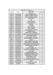
...-1 268711-2 346811 349480 352111 352113 352115 35211A 352380 352390 354210 359012 550140 554030 554160 559011 567502 731273 749740 W0CZZ W48602 Replacement Parts List P/NO RADS - 51B Description 3041A20036G BASE ASSEMBLY,WELD 3091AR6055M CABINET ASSEMBLY,SINGLE 3530AR1615B GRILLE ASSEMBLY,FRONT 3530A10039A GRILLE,INLET 4520AR3191A...CONDENSER ASSEMBLY,FIRST 2520UABC2JA COMPRESSOR SET,KOREA 5901A20011B FAN ASSEMBLY,AXIAL 6750U-L050A OVERLOAD PROTECT 3127A20074A INSTALL PART ASSEMBLY,SINGLE 5210AR3196C 0CZZA20005B GUIDE CAPACITOR,FILM,BOX 3H02932B CLAMP,SPRING REMARK...
...-1 268711-2 346811 349480 352111 352113 352115 35211A 352380 352390 354210 359012 550140 554030 554160 559011 567502 731273 749740 W0CZZ W48602 Replacement Parts List P/NO RADS - 51B Description 3041A20036G BASE ASSEMBLY,WELD 3091AR6055M CABINET ASSEMBLY,SINGLE 3530AR1615B GRILLE ASSEMBLY,FRONT 3530A10039A GRILLE,INLET 4520AR3191A...CONDENSER ASSEMBLY,FIRST 2520UABC2JA COMPRESSOR SET,KOREA 5901A20011B FAN ASSEMBLY,AXIAL 6750U-L050A OVERLOAD PROTECT 3127A20074A INSTALL PART ASSEMBLY,SINGLE 5210AR3196C 0CZZA20005B GUIDE CAPACITOR,FILM,BOX 3H02932B CLAMP,SPRING REMARK...
Service Manual
Page 26
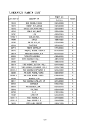
SERVICE PARTS LIST LOCATION NO DESCRIPTION 130410 130910 135312 135313 147581 147582-1 149980 152302 238310 267110 268712 268714 263230 346811 349480 35211A 352113 ... UPPER ISOLATOR,COMP TUBE ASSEMBLY,CAPILLARY OUT COMPRESSOR FAN ASSEMBLY,AXIAL FAN,TURBO O.L.P CAPACITOR Frame ASSEMBLY L Frame ASSEMBLY R UPPER GUIDE CABINET PART NO RAD-61A 3041A20036N 3091AR6055M 3531A20087B 3530A10039A 4520AR3191A 5990AR3190C 4998A10025A 5231AR2148A 3831A10001F 6711A20066C 6871A20432B 6871A10123F 6323A20003S 4681A10016M 4948A10016B 5211A10062G 5210A21748B 5210A10063E 5990AR3190D 5239A30003G 2520UCAA004 ...
SERVICE PARTS LIST LOCATION NO DESCRIPTION 130410 130910 135312 135313 147581 147582-1 149980 152302 238310 267110 268712 268714 263230 346811 349480 35211A 352113 ... UPPER ISOLATOR,COMP TUBE ASSEMBLY,CAPILLARY OUT COMPRESSOR FAN ASSEMBLY,AXIAL FAN,TURBO O.L.P CAPACITOR Frame ASSEMBLY L Frame ASSEMBLY R UPPER GUIDE CABINET PART NO RAD-61A 3041A20036N 3091AR6055M 3531A20087B 3530A10039A 4520AR3191A 5990AR3190C 4998A10025A 5231AR2148A 3831A10001F 6711A20066C 6871A20432B 6871A10123F 6323A20003S 4681A10016M 4948A10016B 5211A10062G 5210A21748B 5210A10063E 5990AR3190D 5239A30003G 2520UCAA004 ...


