

Service Manual
Page 2
... Requirements ...9 Installation Kits Contents (some models including installation kit 10 Suggested tool Requirements...10 Cabinet Installation...11 Operation ...13 Disassembly instructions...14 Mechanical parts ...14 Air Handling Parts ...15 Electrical Parts ...16 Refrigeration cycle ...19 Schematic Diagram...22 Troubleshooting guide...23 Piping System ...23 Troubleshooting guide ...24 Room Air Conditioner Voltage Limits...26...
... Requirements ...9 Installation Kits Contents (some models including installation kit 10 Suggested tool Requirements...10 Cabinet Installation...11 Operation ...13 Disassembly instructions...14 Mechanical parts ...14 Air Handling Parts ...15 Electrical Parts ...16 Refrigeration cycle ...19 Schematic Diagram...22 Troubleshooting guide...23 Piping System ...23 Troubleshooting guide ...24 Room Air Conditioner Voltage Limits...26...

Service Manual
Page 8
... tube. The green wire must be no obstacle, like a fence, within 20" which might restrict heat radiation from the front grille with separating the hinged part by inserting a straight type screw-driver tip (b). 4. FOAM COOLED AIR How to an independent circuit. BEFORE ATTACHING THE FRONT GRILLE TO THE CABINET, IF YOU...
... tube. The green wire must be no obstacle, like a fence, within 20" which might restrict heat radiation from the front grille with separating the hinged part by inserting a straight type screw-driver tip (b). 4. FOAM COOLED AIR How to an independent circuit. BEFORE ATTACHING THE FRONT GRILLE TO THE CABINET, IF YOU...

Service Manual
Page 9
Installation Window Requirements NOTICE All supporting parts should be less than 1 1/4". The top and bottom window sashes must be secured to firm wood, masonry, or metal. • WINDOW REQUIREMENTS 1. Installation Kits Contents (...
Installation Window Requirements NOTICE All supporting parts should be less than 1 1/4". The top and bottom window sashes must be secured to firm wood, masonry, or metal. • WINDOW REQUIREMENTS 1. Installation Kits Contents (...

Service Manual
Page 14
... control box forward completely. 7. Remove the front grille. (Refer to the wiring diagram found on page 29~30 in the control box. 6. Disassembly Disassembly - Mechanical parts 1. Pull the base pan forward. Cabinet 1. Figure 16 3. Front grille 1. Open the inlet grille upward or downward. 2. Re-install the component by placing a 20,000...
... control box forward completely. 7. Remove the front grille. (Refer to the wiring diagram found on page 29~30 in the control box. 6. Disassembly Disassembly - Mechanical parts 1. Pull the base pan forward. Cabinet 1. Figure 16 3. Front grille 1. Open the inlet grille upward or downward. 2. Re-install the component by placing a 20,000...

Service Manual
Page 15
... the components by referring to section 1) 2. Remove the cabinet. (Refer to section 4) 2. Figure 20 Figure 21 Disassembly 15 Room Air Conditioner Figure 22 Air handling parts 4. Remove the front grille. (Refer to the removal procedure, above . Cover (at the left side and the top side.(See Fig. 19) 3. Remove the Heater...
... the components by referring to section 1) 2. Remove the cabinet. (Refer to section 4) 2. Figure 20 Figure 21 Disassembly 15 Room Air Conditioner Figure 22 Air handling parts 4. Remove the front grille. (Refer to the removal procedure, above . Cover (at the left side and the top side.(See Fig. 19) 3. Remove the Heater...

Service Manual
Page 16
.... 24) 4. Re-install the component by referring to the removal procedure, above . Remove the motor. 7. Discharge the refrigerant system using FreonTM Recovery System. Shroud 1. Electrical parts 8. Remove the cover control and disconnect a wire hous- Remove the 4 screws which fasten the compressor. (See Fig. 26) 6. Leave the valve in control box. (Refer...
.... 24) 4. Re-install the component by referring to the removal procedure, above . Remove the motor. 7. Discharge the refrigerant system using FreonTM Recovery System. Shroud 1. Electrical parts 8. Remove the cover control and disconnect a wire hous- Remove the 4 screws which fasten the compressor. (See Fig. 26) 6. Leave the valve in control box. (Refer...

Service Manual
Page 27
... and rearrange tubing not to be cooled. Check terminals. Compressor cycles on overload. Replace thermostat if circuit is hitting air guide, rearrange the air handling parts. Replace if not within limits, call an electrician. If open . If condenser fins are closed over a large area on overload. Close if open or grounded...
... and rearrange tubing not to be cooled. Check terminals. Compressor cycles on overload. Replace thermostat if circuit is hitting air guide, rearrange the air handling parts. Replace if not within limits, call an electrician. If open . If condenser fins are closed over a large area on overload. Close if open or grounded...
Service Manual
Page 29
LWHD1800HR LWHD2400HR 3041A30002Y 3091AR6057X 3530AR1604A 3531A20073W 3551A30015A 3720AR6163A 2H01102A 4758AR7264C 4758AR7278C 4758AR6157A 4800AR7271A 4998AR1597A 5231AR6159A 3831A10018M 4995A20186C 6411A20051G 6323A20003F 6871A20195V 6871A10188C 6711A20034D 4681AR6033K 4900AR7265A 4960AR1596A 5211AR7059A ... ASSEMBLY, AXIAL 753000 HEATER, ELECTRIC 753010 HEATER ASSEMBLY, ELECTRIC W0CZZ CAPACITOR, DRAWING W48602 CLAMP, SPRING 325115-1 TUBE, EVAPORATOR 325115-2 TUBE, EVAPORATOR 29 Room Air Conditioner PART NO. Replacement Parts List Replacement Parts List LOCATION NO.
LWHD1800HR LWHD2400HR 3041A30002Y 3091AR6057X 3530AR1604A 3531A20073W 3551A30015A 3720AR6163A 2H01102A 4758AR7264C 4758AR7278C 4758AR6157A 4800AR7271A 4998AR1597A 5231AR6159A 3831A10018M 4995A20186C 6411A20051G 6323A20003F 6871A20195V 6871A10188C 6711A20034D 4681AR6033K 4900AR7265A 4960AR1596A 5211AR7059A ... ASSEMBLY, AXIAL 753000 HEATER, ELECTRIC 753010 HEATER ASSEMBLY, ELECTRIC W0CZZ CAPACITOR, DRAWING W48602 CLAMP, SPRING 325115-1 TUBE, EVAPORATOR 325115-2 TUBE, EVAPORATOR 29 Room Air Conditioner PART NO. Replacement Parts List Replacement Parts List LOCATION NO.

Service Manual
Page 30
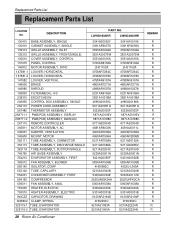
Replacement Parts List Replacement Parts List LOCATION NO. 130410 130910 135314 135312 135510 137215 146812 147581-1 147581-2 147582 148000 149980 159830 238310 249950 264110 567480 268711-1...,ELECTRIC HEATER ASSEMBLY,ELECTRIC CAPACITOR,DRAWING CLAMP,SPRING TUBE,EVAPORATOR TUBE,EVAPORATOR 135500 COVER 731273 INSTALL PART ASSEMBLY,SINGLE 749740 135515 GUIDE COVER ASSEMBLY,TOP(INDOOR) 30 Room Air Conditioner PART NO(2007) LWHD1807HR LWHD2400HRY7 3041A23004F 3041A23004H 3091AR6056Q 3091AR6056Q 3530AR1604A 3530AR1604A 3531A20073W 3531A20073W 3551A30015A 3551A30015A 3720AR6163A 3720AR6163A...
Replacement Parts List Replacement Parts List LOCATION NO. 130410 130910 135314 135312 135510 137215 146812 147581-1 147581-2 147582 148000 149980 159830 238310 249950 264110 567480 268711-1...,ELECTRIC HEATER ASSEMBLY,ELECTRIC CAPACITOR,DRAWING CLAMP,SPRING TUBE,EVAPORATOR TUBE,EVAPORATOR 135500 COVER 731273 INSTALL PART ASSEMBLY,SINGLE 749740 135515 GUIDE COVER ASSEMBLY,TOP(INDOOR) 30 Room Air Conditioner PART NO(2007) LWHD1807HR LWHD2400HRY7 3041A23004F 3041A23004H 3091AR6056Q 3091AR6056Q 3530AR1604A 3530AR1604A 3531A20073W 3531A20073W 3551A30015A 3551A30015A 3720AR6163A 3720AR6163A...


