

Service Manual
Page 1
website http://www.lgservice.com LG LG Room Air Conditioner SERVICE MANUAL MODEL: LWHD1800HR, LWHD2400HR LWHD1807HR, LWHD2400HRY7 CAUTION • BEFORE SERVICING THE UNIT, READ THE SAFETY PRECAUTIONS IN THIS MANUAL. • ONLY FOR AUTHORIZED SERVICE PERSONNEL.
website http://www.lgservice.com LG LG Room Air Conditioner SERVICE MANUAL MODEL: LWHD1800HR, LWHD2400HR LWHD1807HR, LWHD2400HRY7 CAUTION • BEFORE SERVICING THE UNIT, READ THE SAFETY PRECAUTIONS IN THIS MANUAL. • ONLY FOR AUTHORIZED SERVICE PERSONNEL.

Service Manual
Page 2
... kit 10 Suggested tool Requirements...10 Cabinet Installation...11 Operation ...13 Disassembly instructions...14 Mechanical parts ...14 Air Handling Parts ...15 Electrical Parts ...16 Refrigeration cycle ...19 Schematic Diagram...22 Troubleshooting guide...23 Piping System ...23 Troubleshooting guide ...24 Room Air Conditioner Voltage Limits...26 Exploded View...28 Replacement Parts List ...29 2 Room...
... kit 10 Suggested tool Requirements...10 Cabinet Installation...11 Operation ...13 Disassembly instructions...14 Mechanical parts ...14 Air Handling Parts ...15 Electrical Parts ...16 Refrigeration cycle ...19 Schematic Diagram...22 Troubleshooting guide...23 Piping System ...23 Troubleshooting guide ...24 Room Air Conditioner Voltage Limits...26 Exploded View...28 Replacement Parts List ...29 2 Room...

Service Manual
Page 4
... sure the installation area does not deteriorate with age. • If the base collapses, the air conditioner could cause injury. Do not store or use flammable gas or combustibles near the air conditioner. • Sharp edges could fall with it, causing property damage, product failure, and personal ...injury. 4 Room Air Conditioner Safety Precautions Do not modify or extend the power cord. • There ...
... sure the installation area does not deteriorate with age. • If the base collapses, the air conditioner could cause injury. Do not store or use flammable gas or combustibles near the air conditioner. • Sharp edges could fall with it, causing property damage, product failure, and personal ...injury. 4 Room Air Conditioner Safety Precautions Do not modify or extend the power cord. • There ...

Service Manual
Page 5
This symbol alerts you to the air conditioner. NOTICE This symbol indicates special notes. Outside Dimensions Dimensions D W H Dimension W H D Model mm(inch) mm(inch) mm(inch) LWHD1800HR 660 (26) 428 (16 27/32) 675 (26 9/16) LWHD2400HR 660 (26) 428 (16 27/32) 770 (30 5/16) Service Manual 5 Dimensions Symbols Used in this Manual This symbol alerts you to hazards that could cause harm to the risk of electric shock.
This symbol alerts you to the air conditioner. NOTICE This symbol indicates special notes. Outside Dimensions Dimensions D W H Dimension W H D Model mm(inch) mm(inch) mm(inch) LWHD1800HR 660 (26) 428 (16 27/32) 675 (26 9/16) LWHD2400HR 660 (26) 428 (16 27/32) 770 (30 5/16) Service Manual 5 Dimensions Symbols Used in this Manual This symbol alerts you to hazards that could cause harm to the risk of electric shock.

Service Manual
Page 6
Specfications Product Specifications ITEMS MODELS LWHD1800HR LWHD2400HR POWER SUPPLY 1Ø, 208/230V, 60Hz 1Ø, 208/230V, 60Hz COOLING CAPACITY (Btu/h)...FAN/COOLING/HEATING 1 / 2 / 2 1 / 2 / 2 FAN MOTOR 6 POLES OPERATION CONTROL TOUCH PANEL ROOM TEMP. CONTROL THERMISTOR AIR DIRECTION CONTROL VERTICAL LOUVER(RIGHT&LEFT) HORIZONTAL LOUVER(UP&DOWN) CONSTRUCTION SLIDE IN-OUT CHASSIS ELECTRIC HEATER 3.5KW, 230V COMPRESSOR INTERNAL OVERLOAD PROTECTOR ... Quality on the produst since this specification may be changed for improving performance. 6 Room Air Conditioner
Specfications Product Specifications ITEMS MODELS LWHD1800HR LWHD2400HR POWER SUPPLY 1Ø, 208/230V, 60Hz 1Ø, 208/230V, 60Hz COOLING CAPACITY (Btu/h)...FAN/COOLING/HEATING 1 / 2 / 2 1 / 2 / 2 FAN MOTOR 6 POLES OPERATION CONTROL TOUCH PANEL ROOM TEMP. CONTROL THERMISTOR AIR DIRECTION CONTROL VERTICAL LOUVER(RIGHT&LEFT) HORIZONTAL LOUVER(UP&DOWN) CONSTRUCTION SLIDE IN-OUT CHASSIS ELECTRIC HEATER 3.5KW, 230V COMPRESSOR INTERNAL OVERLOAD PROTECTOR ... Quality on the produst since this specification may be changed for improving performance. 6 Room Air Conditioner

Service Manual
Page 7
... BLOWER FAN, OUTDOOR PROPELLER TYPE FAN WITH SLINGER-RING FAN SPEEDS, FAN/COOLING/HEATING 1 / 2 / 2 1 / 2 / 2 FAN MOTOR 6 POLES OPERATION CONTROL TOUCH PANEL ROOM TEMP. CONTROL THERMISTOR AIR DIRECTION CONTROL VERTICAL LOUVER(RIGHT&LEFT) HORIZONTAL LOUVER(UP&DOWN) CONSTRUCTION SLIDE IN-OUT CHASSIS ELECTRIC HEATER 3.5KW, 230V COMPRESSOR INTERNAL OVERLOAD PROTECTOR PROTECTOR FAN... * DB:Dry Bulb ** WB:Wet Bulb NOTE: Please refer to Label Quality on the produst since this specification may be changed for improving performance. 7 Room Air Conditioner
... BLOWER FAN, OUTDOOR PROPELLER TYPE FAN WITH SLINGER-RING FAN SPEEDS, FAN/COOLING/HEATING 1 / 2 / 2 1 / 2 / 2 FAN MOTOR 6 POLES OPERATION CONTROL TOUCH PANEL ROOM TEMP. CONTROL THERMISTOR AIR DIRECTION CONTROL VERTICAL LOUVER(RIGHT&LEFT) HORIZONTAL LOUVER(UP&DOWN) CONSTRUCTION SLIDE IN-OUT CHASSIS ELECTRIC HEATER 3.5KW, 230V COMPRESSOR INTERNAL OVERLOAD PROTECTOR PROTECTOR FAN... * DB:Dry Bulb ** WB:Wet Bulb NOTE: Please refer to Label Quality on the produst since this specification may be changed for improving performance. 7 Room Air Conditioner

Service Manual
Page 9
...) Left frame curtain Frame guide(2) Window locking bracket Sill bracket(2) Support bracket(2) Right frame curtain Type A (14) Type B (7) Type C (5) Type D (2) Carriage Bolt (2) Lock Nut (4) 9 Room Air Conditioner Installation Window Requirements NOTICE All supporting parts should be less than 1 1/4".
...) Left frame curtain Frame guide(2) Window locking bracket Sill bracket(2) Support bracket(2) Right frame curtain Type A (14) Type B (7) Type C (5) Type D (2) Carriage Bolt (2) Lock Nut (4) 9 Room Air Conditioner Installation Window Requirements NOTICE All supporting parts should be less than 1 1/4".

Service Manual
Page 11
... Top retainer bar Figure 7 Window stool Front angle Window sash Top retainer bar Foam-PE Cabinet Frame curtain Foam-PE Figure 8 Sash track 11 Room Air Conditioner Figure 9 Front Angle Screw(Type B) The cabinet should be installed with approximately 1/2" of water in the bottom pan. NOTICE 1. Using the M-screw and the lock...
... Top retainer bar Figure 7 Window stool Front angle Window sash Top retainer bar Foam-PE Cabinet Frame curtain Foam-PE Figure 8 Sash track 11 Room Air Conditioner Figure 9 Front Angle Screw(Type B) The cabinet should be installed with approximately 1/2" of water in the bottom pan. NOTICE 1. Using the M-screw and the lock...

Service Manual
Page 12
Slide the unit into the tabs on the front of room air conditioner is now completed. Attach the Window locking bracket with a screw (Type A) through the front grille. (See Fig. 14) 12. Attach each window sash track, and ...
Slide the unit into the tabs on the front of room air conditioner is now completed. Attach the Window locking bracket with a screw (Type A) through the front grille. (See Fig. 14) 12. Attach each window sash track, and ...

Service Manual
Page 13
... can be in the CLOSE position in the room, set the ventilation lever to the OPEN position. POWER BUTTON To turn the air conditioner OFF, push the button again. ENERGY SAVER The fan stops when the compressor stops cooling. Approximately every 3 munutes the fan will... disappear quickly. 13 Room Air Conditioner This button takes priority over . The temperature can automatically control the air flow direction. 7. REMOCON SIGNAL RECEIVER CAUTION: A slight heat odor may come from the unit when ...
... can be in the CLOSE position in the room, set the ventilation lever to the OPEN position. POWER BUTTON To turn the air conditioner OFF, push the button again. ENERGY SAVER The fan stops when the compressor stops cooling. Approximately every 3 munutes the fan will... disappear quickly. 13 Room Air Conditioner This button takes priority over . The temperature can automatically control the air flow direction. 7. REMOCON SIGNAL RECEIVER CAUTION: A slight heat odor may come from the unit when ...

Service Manual
Page 15
...fasten the evaporator at the top) 1. Remove the blower with plier. (See Fig. 21) 9. Move the evaporator sideward carefully. 4. Remove the orifice from the air guide carefully. (See Fig. 21) 8. Remove the cabinet. (Refer to section 4) 2. Remove the covers and the brace. (See Fig. 19) 5. ... without touching blades. (See Fig. 22) 10. Remove the Heater Cover.(See Fig. 20) 7. Figure 20 Figure 21 Disassembly 15 Room Air Conditioner Figure 22 Air handling parts 4. Remove the cover. (Refer to section 2) 3. Re-install the components by referring to the removal procedure, above . Remove ...
...fasten the evaporator at the top) 1. Remove the blower with plier. (See Fig. 21) 9. Move the evaporator sideward carefully. 4. Remove the orifice from the air guide carefully. (See Fig. 21) 8. Remove the cabinet. (Refer to section 4) 2. Remove the covers and the brace. (See Fig. 19) 5. ... without touching blades. (See Fig. 22) 10. Remove the Heater Cover.(See Fig. 20) 7. Figure 20 Figure 21 Disassembly 15 Room Air Conditioner Figure 22 Air handling parts 4. Remove the cover. (Refer to section 2) 3. Re-install the components by referring to the removal procedure, above . Remove ...

Service Manual
Page 17
... the control box. (Refer to the unit.) Figure 28 12. Unfold the control box. (Refer to the removal procedure above. (See Figure 30) 17 Room Air Conditioner Figure 29 Disassembly 10. Remove a screw and unfold the control box. (See Fig. 27) 5. Disconnect the thermistor terminals from the rocker switch and remove the...
... the control box. (Refer to the unit.) Figure 28 12. Unfold the control box. (Refer to the removal procedure above. (See Figure 30) 17 Room Air Conditioner Figure 29 Disassembly 10. Remove a screw and unfold the control box. (See Fig. 27) 5. Disconnect the thermistor terminals from the rocker switch and remove the...

Service Manual
Page 19
... notes. Remove 2 screws which fasten the evaporator at the capillary tube. 4. Discharge the refrigerant completely. 4. Remove the brace. (Refer to section 2) 2. Figure 32 19 Room Air Conditioner Remove the 5 or 6 screws which fasten the condenser. 5. Remove the top cover and the brace. (Refer to section 2) 2. Remove the cabinet. (Refer to section 4) 3. Remove...
... notes. Remove 2 screws which fasten the evaporator at the capillary tube. 4. Discharge the refrigerant completely. 4. Remove the brace. (Refer to section 2) 2. Figure 32 19 Room Air Conditioner Remove the 5 or 6 screws which fasten the condenser. 5. Remove the top cover and the brace. (Refer to section 2) 2. Remove the cabinet. (Refer to section 4) 3. Remove...

Service Manual
Page 21
Disassembly Equipment needed: Vacuum pump, Charging cylinder, Manifold gauge, Brazing equipment. CONDENSER (HIGH PRESSURE SIDE) COMPOUND GAUGE MANIFOLD GAUGE B A CAPILLARY TUBE SEE INSETS BELOW EVAPORATOR (LOW PRESSURE SIDE) COMPRESSOR A B EXTERNAL VACUUM PUMP Figure 31A-Pulling Vacuum 21 Room Air Conditioner LOW HI B A CHARGING CYLINDER C Figure 31B-Charging Pin-off tool capable of making a leak-proof seal, Leak detector, Tubing cutter, Hand Tools to remove components, Service valve.
Disassembly Equipment needed: Vacuum pump, Charging cylinder, Manifold gauge, Brazing equipment. CONDENSER (HIGH PRESSURE SIDE) COMPOUND GAUGE MANIFOLD GAUGE B A CAPILLARY TUBE SEE INSETS BELOW EVAPORATOR (LOW PRESSURE SIDE) COMPRESSOR A B EXTERNAL VACUUM PUMP Figure 31A-Pulling Vacuum 21 Room Air Conditioner LOW HI B A CHARGING CYLINDER C Figure 31B-Charging Pin-off tool capable of making a leak-proof seal, Leak detector, Tubing cutter, Hand Tools to remove components, Service valve.

Service Manual
Page 23
... in what is called the refrigeration system. ROOM AIR CONITIONER CYCLE OF REFRIGERATION EVAPORATOR COILS COOLED AIR COMPLETE LIQUID BOIL OFF POINT SUCTION LINE COOL LOW PRESSURE VAPOR ROOM AIR HEAT LOAD CONDENSER COILS VAPOR INLET HOT DISCHARGED AIR LIQUID PRESSURE DROP 23 Room Air Conditioner MOTOR OUTSIDE COOLING AIR FOR REFRIGERANT PASS THROUGH COMPRESSOR OIL (LIQUID...
... in what is called the refrigeration system. ROOM AIR CONITIONER CYCLE OF REFRIGERATION EVAPORATOR COILS COOLED AIR COMPLETE LIQUID BOIL OFF POINT SUCTION LINE COOL LOW PRESSURE VAPOR ROOM AIR HEAT LOAD CONDENSER COILS VAPOR INLET HOT DISCHARGED AIR LIQUID PRESSURE DROP 23 Room Air Conditioner MOTOR OUTSIDE COOLING AIR FOR REFRIGERANT PASS THROUGH COMPRESSOR OIL (LIQUID...

Service Manual
Page 25
... fuse. Loose terminal connection. Irregular motor resistance ( ). Replacement of control switch setting. Irregular motor resistance ( ) Irregular motor insulation ( ) Replacement of compressor (Motor damaged) 25 Room Air Conditioner Regular but fails to start.
... fuse. Loose terminal connection. Irregular motor resistance ( ). Replacement of control switch setting. Irregular motor resistance ( ) Irregular motor insulation ( ) Replacement of compressor (Motor damaged) 25 Room Air Conditioner Regular but fails to start.

Service Manual
Page 26
Troubleshooting Guide Room Air Conditioner Voltage Limits NAME PLATE RATING 208~230±10% 115±10% MINIMUM 187V 104V MAXIMUM 253V 126V COMPLAINT Fan motor will not rotate, replace ...
Troubleshooting Guide Room Air Conditioner Voltage Limits NAME PLATE RATING 208~230±10% 115±10% MINIMUM 187V 104V MAXIMUM 253V 126V COMPLAINT Fan motor will not rotate, replace ...

Service Manual
Page 27
...if externally mounted. Replace if open circuit. 27 Room Air Conditioner Clean the interior base before servicing.) Compressor Overload Voltage Overload Fan motor Condenser air flow restriction Condenser fins (damaged) Capacitor Wiring Refrigerating system Air filter Exhaust damper door Unit undersized Blower or fan Check... on the coil surface, head pressures will not run, but fan motor runs. Replace thermostat if circuit is hitting air guide, rearrange the air handling parts. Replace if shorted, open . Remove the cabinet. If condenser fins are closed over a large area ...
...if externally mounted. Replace if open circuit. 27 Room Air Conditioner Clean the interior base before servicing.) Compressor Overload Voltage Overload Fan motor Condenser air flow restriction Condenser fins (damaged) Capacitor Wiring Refrigerating system Air filter Exhaust damper door Unit undersized Blower or fan Check... on the coil surface, head pressures will not run, but fan motor runs. Replace thermostat if circuit is hitting air guide, rearrange the air handling parts. Replace if shorted, open . Remove the cabinet. If condenser fins are closed over a large area ...
Service Manual
Page 29
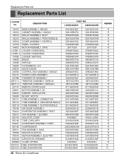
Replacement Parts List Replacement Parts List LOCATION NO. LWHD1800HR LWHD2400HR 3041A30002Y 3091AR6057X 3530AR1604A 3531A20073W 3551A30015A 3720AR6163A 2H01102A 4758AR7264C 4758AR7278C 4758AR6157A ...AIR GUIDE ASSEMBLY 354210 EVAPORATOR ASSEMBLY, FIRST 359012 FAN ASSEMBLY, BLOWER 550140 ISOLATOR, COMP 552102 TUBE, CAPILLARY 554031 CONDENSER ASSEMBLY, FIRST 554160 COMPRESSOR 559011 FAN ASSEMBLY, AXIAL 753000 HEATER, ELECTRIC 753010 HEATER ASSEMBLY, ELECTRIC W0CZZ CAPACITOR, DRAWING W48602 CLAMP, SPRING 325115-1 TUBE, EVAPORATOR 325115-2 TUBE, EVAPORATOR 29 Room Air Conditioner...
Replacement Parts List Replacement Parts List LOCATION NO. LWHD1800HR LWHD2400HR 3041A30002Y 3091AR6057X 3530AR1604A 3531A20073W 3551A30015A 3720AR6163A 2H01102A 4758AR7264C 4758AR7278C 4758AR6157A ...AIR GUIDE ASSEMBLY 354210 EVAPORATOR ASSEMBLY, FIRST 359012 FAN ASSEMBLY, BLOWER 550140 ISOLATOR, COMP 552102 TUBE, CAPILLARY 554031 CONDENSER ASSEMBLY, FIRST 554160 COMPRESSOR 559011 FAN ASSEMBLY, AXIAL 753000 HEATER, ELECTRIC 753010 HEATER ASSEMBLY, ELECTRIC W0CZZ CAPACITOR, DRAWING W48602 CLAMP, SPRING 325115-1 TUBE, EVAPORATOR 325115-2 TUBE, EVAPORATOR 29 Room Air Conditioner...

Service Manual
Page 30
...,ELECTRIC CAPACITOR,DRAWING CLAMP,SPRING TUBE,EVAPORATOR TUBE,EVAPORATOR 135500 COVER 731273 INSTALL PART ASSEMBLY,SINGLE 749740 135515 GUIDE COVER ASSEMBLY,TOP(INDOOR) 30 Room Air Conditioner PART NO(2007) LWHD1807HR LWHD2400HRY7 3041A23004F 3041A23004H 3091AR6056Q 3091AR6056Q 3530AR1604A 3530AR1604A 3531A20073W 3531A20073W 3551A30015A 3551A30015A 3720AR6163A 3720AR6163A 2H01102J 2H01102J 4758AR7264C 4758AR7264C 4758AR7278C 4758AR7278C 4758AR6157A 4758AR6157B...
...,ELECTRIC CAPACITOR,DRAWING CLAMP,SPRING TUBE,EVAPORATOR TUBE,EVAPORATOR 135500 COVER 731273 INSTALL PART ASSEMBLY,SINGLE 749740 135515 GUIDE COVER ASSEMBLY,TOP(INDOOR) 30 Room Air Conditioner PART NO(2007) LWHD1807HR LWHD2400HRY7 3041A23004F 3041A23004H 3091AR6056Q 3091AR6056Q 3530AR1604A 3530AR1604A 3531A20073W 3531A20073W 3551A30015A 3551A30015A 3720AR6163A 3720AR6163A 2H01102J 2H01102J 4758AR7264C 4758AR7264C 4758AR7278C 4758AR7278C 4758AR6157A 4758AR6157B...


