
User Guide
Page 7
...for more detaffs. 4. PIug in the power cord properIy. 2. See page 1i for details or call (800) 243-_. i. Do not use this manual.. 7 The air conditioner is damaged and requires replacement, have an Authorized Se_-lcer install an exact replacement part. !. There is a possibffi_ of injury...Do not touch the metal parts of this air condi_oner for an extended period of time. 2. The fan rotates at a very high speed during operation. Use a dedi circuit. Do net use an extension cord. Do not start/stop o_ration by pluggin_unplugging the power cord. 5. Have your health...
...for more detaffs. 4. PIug in the power cord properIy. 2. See page 1i for details or call (800) 243-_. i. Do not use this manual.. 7 The air conditioner is damaged and requires replacement, have an Authorized Se_-lcer install an exact replacement part. !. There is a possibffi_ of injury...Do not touch the metal parts of this air condi_oner for an extended period of time. 2. The fan rotates at a very high speed during operation. Use a dedi circuit. Do net use an extension cord. Do not start/stop o_ration by pluggin_unplugging the power cord. 5. Have your health...

User Guide
Page 17
...~_F The unittakes an average_ _ minutesto,adjust_e room_mperatu_ _ I°E REM_E CONTROLSENSOR _ne_ Manual 17 Se_ dry mode for er_y _ng Se_d _n mode _r _sic venti[ati_ _n op_t_on. The _ntmls look like this: OperaUng instructions Operation s_ when this b_on is pmss_ _d stops w_n you p_ss the bu_ again.... M_ ONJOFF T!MER The timer can be set to maintain _e d_ired tem_rature. OPERATION MODE SE_,_R Se_t _li_ mode to _ the _m. _ct ener_j _r mode for dry operation. _MPERATURE COiNTROL _e therm_at monit_s _om temp_m to start a_ stop_e unit in h_fly incremen_ ,(upto 12 ...
...~_F The unittakes an average_ _ minutesto,adjust_e room_mperatu_ _ I°E REM_E CONTROLSENSOR _ne_ Manual 17 Se_ dry mode for er_y _ng Se_d _n mode _r _sic venti[ati_ _n op_t_on. The _ntmls look like this: OperaUng instructions Operation s_ when this b_on is pmss_ _d stops w_n you p_ss the bu_ again.... M_ ONJOFF T!MER The timer can be set to maintain _e d_ired tem_rature. OPERATION MODE SE_,_R Se_t _li_ mode to _ the _m. _ct ener_j _r mode for dry operation. _MPERATURE COiNTROL _e therm_at monit_s _om temp_m to start a_ stop_e unit in h_fly incremen_ ,(upto 12 ...

Service Manual
Page 2
Air Conditioner Service Manual TABLE OF CONTENTS Safety Precautions...3 Dimensions ...5 Outside dimensions...5 Product Specifications ...6 Installation ...7 Select the Best Location ...7 Installation Check ...7 How to Secure the Drain Pipe ...7 How to Install...8 Cabinet Installation...9 Operation ...11 Function of Controls ...11 Disassembly ...12 Mechanical Parts...12 Air Handling Parts ...13 Electrical Parts ...14 Refrigerating Cycle...16...
Air Conditioner Service Manual TABLE OF CONTENTS Safety Precautions...3 Dimensions ...5 Outside dimensions...5 Product Specifications ...6 Installation ...7 Select the Best Location ...7 Installation Check ...7 How to Secure the Drain Pipe ...7 How to Install...8 Cabinet Installation...9 Operation ...11 Function of Controls ...11 Disassembly ...12 Mechanical Parts...12 Air Handling Parts ...13 Electrical Parts ...14 Refrigerating Cycle...16...

Service Manual
Page 3
WARNING This symbol indicates the possibility of symbols used in this manual are as shown below. s Incorrect operation due to follow the instruction. s Meanings of death or serious injury. Safety Precautions Safety Precautions To prevent injury to the user or other...instructions must be followed. Always use damaged power cord plugs, or a loose socket. The seriousness is risk of injury or damage to do. Service Manual 3 Be sure to ignoring instruction will cause harm or damage. CAUTION This symbol indicates the possibility of electric shock. Be sure not to properties ...
WARNING This symbol indicates the possibility of symbols used in this manual are as shown below. s Incorrect operation due to follow the instruction. s Meanings of death or serious injury. Safety Precautions Safety Precautions To prevent injury to the user or other...instructions must be followed. Always use damaged power cord plugs, or a loose socket. The seriousness is risk of injury or damage to do. Service Manual 3 Be sure to ignoring instruction will cause harm or damage. CAUTION This symbol indicates the possibility of electric shock. Be sure not to properties ...

Service Manual
Page 9
... 4 Window stool Front angle Window sash Top retainer bar Foam-PE Cabinet Frame curtain Foam-PE Figure 5 Sash track Figure 6 Front Angle Screw(Type B) Service Manual 9 NOTICE 1. Cabinet Installation 1. Carefully place the cabinet on the window stool and align the center mark on the bottom front with the center line marked...
... 4 Window stool Front angle Window sash Top retainer bar Foam-PE Cabinet Frame curtain Foam-PE Figure 5 Sash track Figure 6 Front Angle Screw(Type B) Service Manual 9 NOTICE 1. Cabinet Installation 1. Carefully place the cabinet on the window stool and align the center mark on the bottom front with the center line marked...
Service Manual
Page 11
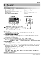
... can be set within a range of 60°F to 86°F by 1°C) Select the lower number for the simple instal- Operation Operation Function of the air conditioner or if there are obstacles between the Remote Control unit and the air conditioner. DISPLAY Cool Energy Saver F1 LOW... state, this button, it will turn off ➔ 1Hour ➔ 2Hours ➔ ... ) 6 REMOCON SIGNAL RECEIVER Service Manual 11 Energy Saver: If Energy Save mode is needed. OPERATION MODE SELECTION BUTTON Every time you push this button controls the time it will turn on or turn on and check...
... can be set within a range of 60°F to 86°F by 1°C) Select the lower number for the simple instal- Operation Operation Function of the air conditioner or if there are obstacles between the Remote Control unit and the air conditioner. DISPLAY Cool Energy Saver F1 LOW... state, this button, it will turn off ➔ 1Hour ➔ 2Hours ➔ ... ) 6 REMOCON SIGNAL RECEIVER Service Manual 11 Energy Saver: If Energy Save mode is needed. OPERATION MODE SELECTION BUTTON Every time you push this button controls the time it will turn on or turn on and check...

Service Manual
Page 17
... With valve C open . 4. Do not add the liquid refrigerant to 30 lbs. allow pressure to rise to the Lowside. d. and c. Service Manual 17 NOTICE - After discharging the unit completely, remove the desired component, and unbraze the pinch-off tube closed. The vacuum pump is no valve to.... 5) The system is now ready for 20 to the pinch-off tool with the two full turns counterclockwise. CAUTION: If high vacuum equipment is operating correctly, use the pinch-off tube. 14. Turn off tool. Valve B is still closed , stop the vacuum pump. 4) Remove the hose ...
... With valve C open . 4. Do not add the liquid refrigerant to 30 lbs. allow pressure to rise to the Lowside. d. and c. Service Manual 17 NOTICE - After discharging the unit completely, remove the desired component, and unbraze the pinch-off tube closed. The vacuum pump is no valve to.... 5) The system is now ready for 20 to the pinch-off tool with the two full turns counterclockwise. CAUTION: If high vacuum equipment is operating correctly, use the pinch-off tube. 14. Turn off tool. Valve B is still closed , stop the vacuum pump. 4) Remove the hose ...
Service Manual
Page 23
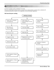
...two kinds. Repair gas leak. Clean condenser. Repair clogging in refrigeration circuit. Service Manual 23 Obstruction at air outlet Correct above trouble Check outdoor coil (heat exchanger) & the fan operation. Check inside gas pressure. Troubleshooting Guide Troubleshooting Guide In general, possible trouble is ... and improper application. Dirty indoor coil (Heat exchanger) Malfunction of fan Clogged of compressor. Satisfactory operation with temperature difference of inlet & outlet air ; 44~50°F(7~10°C) Replacement of refrigerant charged. Adjusting of compressor.
...two kinds. Repair gas leak. Clean condenser. Repair clogging in refrigeration circuit. Service Manual 23 Obstruction at air outlet Correct above trouble Check outdoor coil (heat exchanger) & the fan operation. Check inside gas pressure. Troubleshooting Guide Troubleshooting Guide In general, possible trouble is ... and improper application. Dirty indoor coil (Heat exchanger) Malfunction of fan Clogged of compressor. Satisfactory operation with temperature difference of inlet & outlet air ; 44~50°F(7~10°C) Replacement of refrigerant charged. Adjusting of compressor.

Service Manual
Page 25
... Voltage of Micom DC 5V? Electrical Parts Troubleshooting Guide Troubleshooting Guide Possible Trouble 1 The unit does not operate. YES Is shorted the Trans. YES Replace AC PCB Ass'y. • Check the PCB pattern. Service Manual 25 YES • Replace IC02D. Is the Trans input power AC 115V? NO Is the voltage No...
... Voltage of Micom DC 5V? Electrical Parts Troubleshooting Guide Troubleshooting Guide Possible Trouble 1 The unit does not operate. YES Is shorted the Trans. YES Replace AC PCB Ass'y. • Check the PCB pattern. Service Manual 25 YES • Replace IC02D. Is the Trans input power AC 115V? NO Is the voltage No...

Service Manual
Page 27
...or 15 or 13 NO of AC PCB Ass'y DC 5V? Possible Trouble 4 FAN does not operate. YES • Check the RY-Hi or RY-Med or RY-Lo. • Check the... wiring diagram. YES Is the voltage No.3 of NO CN-AC/DC of IC01M 0V? Service Manual 27 Is the mode NO key pushed once more from cool mode? Troubleshooting Guide • Replace IC01M. •...; Replace IC01M. Possible Trouble 5 The function of AC & DC PCB. YES • Reference to OWNER'S MANUAL. • Set the mode key to Energy Saver mode. • Check the Energy Saver mode key. • Check...
...or 15 or 13 NO of AC PCB Ass'y DC 5V? Possible Trouble 4 FAN does not operate. YES • Check the RY-Hi or RY-Med or RY-Lo. • Check the... wiring diagram. YES Is the voltage No.3 of NO CN-AC/DC of IC01M 0V? Service Manual 27 Is the mode NO key pushed once more from cool mode? Troubleshooting Guide • Replace IC01M. •...; Replace IC01M. Possible Trouble 5 The function of AC & DC PCB. YES • Reference to OWNER'S MANUAL. • Set the mode key to Energy Saver mode. • Check the Energy Saver mode key. • Check...

Service Manual
Page 29
....14 of IC02D NO DC 5V? Is the Trans input power AC 115V? NO (208/230V for LWL1230WAL) ••CChheecckktthheeFFuussee.. ••CChheecckkththeewwiriirninggddiaiaggraramm. . Service Manual 29 YES • Replace the Trans. ElectrIc Parts Troubleshooting Guide Possible Trouble 1 The unit does not...
....14 of IC02D NO DC 5V? Is the Trans input power AC 115V? NO (208/230V for LWL1230WAL) ••CChheecckktthheeFFuussee.. ••CChheecckkththeewwiriirninggddiaiaggraramm. . Service Manual 29 YES • Replace the Trans. ElectrIc Parts Troubleshooting Guide Possible Trouble 1 The unit does not...

Service Manual
Page 31
... DC 5V? YES Is the voltage No.10 NO of Battery NO over 2.3V? Service Manual 31 Is the voltage of CN-AC/DC on AC PCB Ass'y DC 5V? Possible Trouble 5 Remote controller does not operate. YES Is the connection of NO CN-AC/DC OK? Troubleshooting Guide • Replace IC01M...-AC/DC exactly. YES • Check the RY-Hi or RY-Med or RY-Lo. • Check the wiring diagram. Possible Trouble 4 FAN does not operate. YES • Replace Receiver Ass'y.
... DC 5V? YES Is the voltage No.10 NO of Battery NO over 2.3V? Service Manual 31 Is the voltage of CN-AC/DC on AC PCB Ass'y DC 5V? Possible Trouble 5 Remote controller does not operate. YES Is the connection of NO CN-AC/DC OK? Troubleshooting Guide • Replace IC01M...-AC/DC exactly. YES • Check the RY-Hi or RY-Med or RY-Lo. • Check the wiring diagram. Possible Trouble 4 FAN does not operate. YES • Replace Receiver Ass'y.


