
User Guide
Page 2
READ THIS MANUAL inside you a great deal of time and moneyover the lifeof your receiptto this unit. oThis sir conditioner is not Intended for us_ by qualified and ...
READ THIS MANUAL inside you a great deal of time and moneyover the lifeof your receiptto this unit. oThis sir conditioner is not Intended for us_ by qualified and ...

User Guide
Page 7
... power cord is a consumer comfort appliance, not a precision climate contro! Being expos_ to direct airflow for an extended period of time. 2. Do not use this manual.. 7 The air conditioner is damaged and requires replacement, have an Authorized Se_-lcer install an exact replacement part. !. Injuries can destroy the insulation, leading to...
... power cord is a consumer comfort appliance, not a precision climate contro! Being expos_ to direct airflow for an extended period of time. 2. Do not use this manual.. 7 The air conditioner is damaged and requires replacement, have an Authorized Se_-lcer install an exact replacement part. !. Injuries can destroy the insulation, leading to...

User Guide
Page 9
..., The d_i_ should be t_ted on its power supply _d, _ich _st p_er_ gr_ed thr_-prong wall r_p_acle for _=r prot_n agalins| _stibie _ _ pl_ [h_erd., into, Manual 9 a quailed se_i_ Power Su_ly Sta_td _!e '__V, 3-wk_ grounding ra_d 15A, 125V AC U_ i5 AMP.
..., The d_i_ should be t_ted on its power supply _d, _ich _st p_er_ gr_ed thr_-prong wall r_p_acle for _=r prot_n agalins| _stibie _ _ pl_ [h_erd., into, Manual 9 a quailed se_i_ Power Su_ly Sta_td _!e '__V, 3-wk_ grounding ra_d 15A, 125V AC U_ i5 AMP.

User Guide
Page 17
... w_n you p_ss the bu_ again. The therm_tat _n be set be_en 60_F~_F The unittakes an average_ _ minutesto,adjust_e room_mperatu_ _ I°E REM_E CONTROLSENSOR _ne_ Manual 17 FAN SPEED SELECTOR For increas_ powerwhille_oliro, seli_ a high_ _n sp_d. 3 ste_: High --Low-- M_ ONJOFF T!MER The timer can be set to maintain _e...
... w_n you p_ss the bu_ again. The therm_tat _n be set be_en 60_F~_F The unittakes an average_ _ minutesto,adjust_e room_mperatu_ _ I°E REM_E CONTROLSENSOR _ne_ Manual 17 FAN SPEED SELECTOR For increas_ powerwhille_oliro, seli_ a high_ _n sp_d. 3 ste_: High --Low-- M_ ONJOFF T!MER The timer can be set to maintain _e...

User Guide
Page 19
... Adjusti_i the ho_on_! Re_mmended orien_ion of the air ,_nd_nef: Adjusting Horizontal Air FI_ Direction kdjlusti_ the v_l Io_e_ IN and right_11 change horizontalallow. CLOSE_VENT.LOPEN 0 Manual 19 vane up and down _ the va_. Adjusting hodzon_l mr_ Adju_ng ve_| air fl_ Vent Control Forma_mum _llng , CLOSEthe v_t. _is _11a|l_ I_rna| _r...
... Adjusti_i the ho_on_! Re_mmended orien_ion of the air ,_nd_nef: Adjusting Horizontal Air FI_ Direction kdjlusti_ the v_l Io_e_ IN and right_11 change horizontalallow. CLOSE_VENT.LOPEN 0 Manual 19 vane up and down _ the va_. Adjusting hodzon_l mr_ Adju_ng ve_| air fl_ Vent Control Forma_mum _llng , CLOSEthe v_t. _is _11a|l_ I_rna| _r...

User Guide
Page 21
... filter can build up s,lighBy. 3_ Wash _e filter using lukewarm water I_!_ 40 °C (104 °F). 4_ Gently shake _,e ,excess water from the atmosphere. 0 Manual 21
... filter can build up s,lighBy. 3_ Wash _e filter using lukewarm water I_!_ 40 °C (104 °F). 4_ Gently shake _,e ,excess water from the atmosphere. 0 Manual 21

Service Manual
Page 1
website http://www.lgappliances.com LG LG Room Air Conditioner SERVICE MANUAL MODELS: LWHD1500ER,LWHD1800R,L1804R CAUTION • BEFORE SERVICING THE UNIT, READ THE SAFETY PRECAUTIONS IN THIS MANUAL. • ONLY FOR AUTHORIZED SERVICE PERSONNEL.
website http://www.lgappliances.com LG LG Room Air Conditioner SERVICE MANUAL MODELS: LWHD1500ER,LWHD1800R,L1804R CAUTION • BEFORE SERVICING THE UNIT, READ THE SAFETY PRECAUTIONS IN THIS MANUAL. • ONLY FOR AUTHORIZED SERVICE PERSONNEL.

Service Manual
Page 2
Air Conditioner Service Manual TABLE OF CONTENTS Safety Precautions...3 Dimensions ...5 Outside dimensions...5 Product Specifications ...6 Installation ...7 Select the Best Location ...7 Installation Check ...7 How to Secure the Drain Pipe ...7 How to ...
Air Conditioner Service Manual TABLE OF CONTENTS Safety Precautions...3 Dimensions ...5 Outside dimensions...5 Product Specifications ...6 Installation ...7 Select the Best Location ...7 Installation Check ...7 How to Secure the Drain Pipe ...7 How to ...

Service Manual
Page 3
The seriousness is risk of death or serious injury. CAUTION This symbol indicates the possibility of symbols used in this manual are as shown below. Always use damaged power cord plugs, or a loose socket. s Meanings of injury or damage to properties only. Be ... risk of fire or electric shock. • There is classified by the following instructions must be followed. Be sure not to do. Service Manual 3 WARNING This symbol indicates the possibility of electric shock. Safety Precautions Safety Precautions To prevent injury to the user or other people and property ...
The seriousness is risk of death or serious injury. CAUTION This symbol indicates the possibility of symbols used in this manual are as shown below. Always use damaged power cord plugs, or a loose socket. s Meanings of injury or damage to properties only. Be ... risk of fire or electric shock. • There is classified by the following instructions must be followed. Be sure not to do. Service Manual 3 WARNING This symbol indicates the possibility of electric shock. Safety Precautions Safety Precautions To prevent injury to the user or other people and property ...

Service Manual
Page 5
This symbol alerts you to the air conditioner. Dimensions Outside Dimensions D W Cool Energy Saver F1 LOW 'F F2 MED F3 HIGH Fan Dry Timer TEMP MODE TIMER FAN SPEED POWER H Dimension W H D Model mm(inch) mm(inch) mm(inch) HBLG1203R 660(25 31/32) 428(16 27/32) 680(26 27/32) Service Manual 5 Dimensions Symbols Used in this Manual This symbol alerts you to hazards that could cause harm to the risk of electric shock. NOTICE This symbol indicates special notes.
This symbol alerts you to the air conditioner. Dimensions Outside Dimensions D W Cool Energy Saver F1 LOW 'F F2 MED F3 HIGH Fan Dry Timer TEMP MODE TIMER FAN SPEED POWER H Dimension W H D Model mm(inch) mm(inch) mm(inch) HBLG1203R 660(25 31/32) 428(16 27/32) 680(26 27/32) Service Manual 5 Dimensions Symbols Used in this Manual This symbol alerts you to hazards that could cause harm to the risk of electric shock. NOTICE This symbol indicates special notes.

Service Manual
Page 7
... pipe into the hole by pushing down and away from among the following items are not blocked. 5. Connect the drain hose to initial starting. Service Manual 7 FOAM COOLED AIR 30-60" 1/4 Bubble Level AWNING FENCE HEAT RADIATION About 1/2" Over 20" Figure 1 Installation Check The setting conditions must be checked prior to...
... pipe into the hole by pushing down and away from among the following items are not blocked. 5. Connect the drain hose to initial starting. Service Manual 7 FOAM COOLED AIR 30-60" 1/4 Bubble Level AWNING FENCE HEAT RADIATION About 1/2" Over 20" Figure 1 Installation Check The setting conditions must be checked prior to...

Service Manual
Page 9
... 4 Window stool Front angle Window sash Top retainer bar Foam-PE Cabinet Frame curtain Foam-PE Figure 5 Sash track Figure 6 Front Angle Screw(Type B) Service Manual 9 The cabinet should be installed with the center line marked window stool. 3. CAUTION: Do not drill a hole in bottom pan. 4. Be sure the cabinet slants...
... 4 Window stool Front angle Window sash Top retainer bar Foam-PE Cabinet Frame curtain Foam-PE Figure 5 Sash track Figure 6 Front Angle Screw(Type B) Service Manual 9 The cabinet should be installed with the center line marked window stool. 3. CAUTION: Do not drill a hole in bottom pan. 4. Be sure the cabinet slants...
Service Manual
Page 11
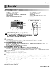
... set as follows. - Every time you push this button controls the time it will turn off ➔ 1Hour ➔ 2Hours ➔ ... ) 6 REMOCON SIGNAL RECEIVER Service Manual 11 Operation Operation Function of Controls • Designed for COOLING ONLY. • Powerful and quiet cooling. • Slide-in adjustable Thermistor • Washable one-touch...
... set as follows. - Every time you push this button controls the time it will turn off ➔ 1Hour ➔ 2Hours ➔ ... ) 6 REMOCON SIGNAL RECEIVER Service Manual 11 Operation Operation Function of Controls • Designed for COOLING ONLY. • Powerful and quiet cooling. • Slide-in adjustable Thermistor • Washable one-touch...

Service Manual
Page 12
... removal procedure, above. (Refer to the removal procedure, above . 3. After disassembling the FRONT GRILLE, remove the 2 screws that connects PCB and motor wire in this manual and on the control box.) TEMP MODE Cool COOL FAN En DRY Saevrgery INDOOR FAN HEAT DEFROST DFrayn Timer DESIRED FPFRFE32U1SENAHMRALSAIEUGOEYVTIRTDWRHFAEOGIRREYTR TIMER SPFAENED ˚C POWER...
... removal procedure, above. (Refer to the removal procedure, above . 3. After disassembling the FRONT GRILLE, remove the 2 screws that connects PCB and motor wire in this manual and on the control box.) TEMP MODE Cool COOL FAN En DRY Saevrgery INDOOR FAN HEAT DEFROST DFrayn Timer DESIRED FPFRFE32U1SENAHMRALSAIEUGOEYVTIRTDWRHFAEOGIRREYTR TIMER SPFAENED ˚C POWER...

Service Manual
Page 13
... removal procedure. Remove the 5 screws that fasten the evaporator. 9. Remove the fan. (See Figure 19) 7. Disassembly Figure 16 Figure 17 Figure 18 Figure 19 Service Manual 13
... removal procedure. Remove the 5 screws that fasten the evaporator. 9. Remove the fan. (See Figure 19) 7. Disassembly Figure 16 Figure 17 Figure 18 Figure 19 Service Manual 13

Service Manual
Page 15
... at the unit.) TEMP MODE CoolCOOL FAN Ene DRY SFavrgery INDOOR FAN HEAT DEFROST Drayn Timer DESIRED PRFEFUFS3EN2A1RASHAEMULYVITIRGOETRFAEDOWHGIRREYTR TIMER SPFAENED ˚C POWER Figure 24 Service Manual 15 Power Cord 1. Open the top cover from the control box. (Refer to section 3) 2. Open the top cover from the capacitor and relay. 5. Re-install...
... at the unit.) TEMP MODE CoolCOOL FAN Ene DRY SFavrgery INDOOR FAN HEAT DEFROST Drayn Timer DESIRED PRFEFUFS3EN2A1RASHAEMULYVITIRGOETRFAEDOWHGIRREYTR TIMER SPFAENED ˚C POWER Figure 24 Service Manual 15 Power Cord 1. Open the top cover from the control box. (Refer to section 3) 2. Open the top cover from the capacitor and relay. 5. Re-install...

Service Manual
Page 17
... vaccum is now ready for a few minutes, then open . Using a tube cutter, cut the pinch-off the unit, allow pressure to enter the system. Service Manual 17 Re-install the components by means of the refrigeration cycle. 1. a. Capillary Tube 1. Evacuate as follows. 1) Connect the vacuum pump, as a WATCO A-1) before venting the...
... vaccum is now ready for a few minutes, then open . Using a tube cutter, cut the pinch-off the unit, allow pressure to enter the system. Service Manual 17 Re-install the components by means of the refrigeration cycle. 1. a. Capillary Tube 1. Evacuate as follows. 1) Connect the vacuum pump, as a WATCO A-1) before venting the...

Service Manual
Page 21
... J20 J10 J13 J19 J18 J11 OSC01B IC03G SW02G TEMP DOWN RECEIVER IC01A SW06G TEMP UP C02L C02A BZ01E J24 J2ZD02F J23 J22 J21 Service Manual 21
... J20 J10 J13 J19 J18 J11 OSC01B IC03G SW02G TEMP DOWN RECEIVER IC01A SW06G TEMP UP C02L C02A BZ01E J24 J2ZD02F J23 J22 J21 Service Manual 21
Service Manual
Page 23
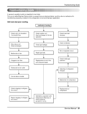
.... Obstruction at air outlet Correct above trouble Check outdoor coil (heat exchanger) & the fan operation. Not on separate circuit. Check clogging in refrigeration circuit. Service Manual 23 The one is called Starting Failure which is caused from an electrical defect, and the other is classified in two kinds. Adjusting of air...
.... Obstruction at air outlet Correct above trouble Check outdoor coil (heat exchanger) & the fan operation. Not on separate circuit. Check clogging in refrigeration circuit. Service Manual 23 The one is called Starting Failure which is caused from an electrical defect, and the other is classified in two kinds. Adjusting of air...

Service Manual
Page 25
... between NO AC and DC OK? YES • Replace D02D~D05D. • Replace IC01D. YES Replace AC PCB Ass'y. • Check the PCB pattern. Service Manual 25 YES • Replace IC02D. NO • Check the Main PCB pattern. NO (The No.14 of Micom DC 5V? Electrical Parts Troubleshooting Guide Troubleshooting...
... between NO AC and DC OK? YES • Replace D02D~D05D. • Replace IC01D. YES Replace AC PCB Ass'y. • Check the PCB pattern. Service Manual 25 YES • Replace IC02D. NO • Check the Main PCB pattern. NO (The No.14 of Micom DC 5V? Electrical Parts Troubleshooting Guide Troubleshooting...


