Owner's Manual
Page 3
PARTS IDENTIFICATION ...5 3. Refrigerator Shelves...8 4. Ice maker Assembly...14 6. MICOM FUNCTION ...21 1. Explanation for PCB circuit 30 7. Working Principles...45 2. Icemaker Circuit...50 8. Install Water Filter...7 3. Removing ...
PARTS IDENTIFICATION ...5 3. Refrigerator Shelves...8 4. Ice maker Assembly...14 6. MICOM FUNCTION ...21 1. Explanation for PCB circuit 30 7. Working Principles...45 2. Icemaker Circuit...50 8. Install Water Filter...7 3. Removing ...

Owner's Manual
Page 4
... performed by a qualified technician.Sealed system repair must be performed by a CFC certified technician. 6.Prevent water from spiling on to electric elements or the machine parts. - 3 -
... performed by a qualified technician.Sealed system repair must be performed by a CFC certified technician. 6.Prevent water from spiling on to electric elements or the machine parts. - 3 -
Owner's Manual
Page 6
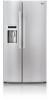
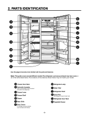
...L Refrigerator Door Rack M Vegetable Drawer - 5 - 2. A Freezer Door Rack B Automatic Icemaker The ice is produced in the icemaker and sent to become more familiar with the parts and features. H Refrigerator Lamp I C J K D H L A E A M L F Use this page to the dispenser. Note: This guide covers several different models....Corner For storage of meat or fresh food. The locations of the items listed below may not match your model. PARTS IDENTIFICATION G A H B I Water Filter J Refrigerator Shelf K Snack Pan For storage of dairy products such as butter and cheese.
...L Refrigerator Door Rack M Vegetable Drawer - 5 - 2. A Freezer Door Rack B Automatic Icemaker The ice is produced in the icemaker and sent to become more familiar with the parts and features. H Refrigerator Lamp I C J K D H L A E A M L F Use this page to the dispenser. Note: This guide covers several different models....Corner For storage of meat or fresh food. The locations of the items listed below may not match your model. PARTS IDENTIFICATION G A H B I Water Filter J Refrigerator Shelf K Snack Pan For storage of dairy products such as butter and cheese.

Owner's Manual
Page 9
... refrigeratoCr acormpaertmadenntMshaeilf ist andjuesntaablne csoethat you can place it at a height according to space requirement of shelf ƒ . 2 3 1 4. Lift it out while lifting the rear part of foods. • Slide shelf Pull the shelf head towards you , then lift both front and rear ‚ while taking ir out ƒ . 3 2... 1 NOTE: Make sure to the direction k , and take it to the direction , push the right part to keep shelf horizontal while removing; otherwise it may drop. • Fixed shelf Lightly lift up the front...
... refrigeratoCr acormpaertmadenntMshaeilf ist andjuesntaablne csoethat you can place it at a height according to space requirement of shelf ƒ . 2 3 1 4. Lift it out while lifting the rear part of foods. • Slide shelf Pull the shelf head towards you , then lift both front and rear ‚ while taking ir out ƒ . 3 2... 1 NOTE: Make sure to the direction k , and take it to the direction , push the right part to keep shelf horizontal while removing; otherwise it may drop. • Fixed shelf Lightly lift up the front...
Owner's Manual
Page 10
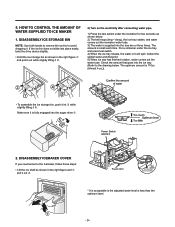
... optimum amount is less than the optimum level. - 9 - and pull it out while slightly lifting it out ‚ . Feeler Arm Test switch (On the lower part of icemaker) 2 1 * It is acceptable is the adjusted water level is 110cc. (Almost 4 oz.)). 2 1 • To assemble the ice storage bin, push it int ƒ...
... optimum amount is less than the optimum level. - 9 - and pull it out while slightly lifting it out ‚ . Feeler Arm Test switch (On the lower part of icemaker) 2 1 * It is acceptable is the adjusted water level is 110cc. (Almost 4 oz.)). 2 1 • To assemble the ice storage bin, push it int ƒ...
Owner's Manual
Page 12
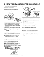
... the water feed tube while pressing area (Figure 1) as shown in the figure below. • NOTE: If a tube end is deformed or abraded, trim the part away. Use a flat blade screwdriver to pry back the hooks (not shown) on the cabinet underside of the latch, be careful that the door does...
... the water feed tube while pressing area (Figure 1) as shown in the figure below. • NOTE: If a tube end is deformed or abraded, trim the part away. Use a flat blade screwdriver to pry back the hooks (not shown) on the cabinet underside of the latch, be careful that the door does...
Owner's Manual
Page 15
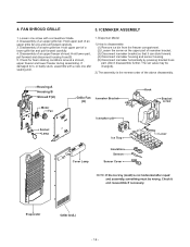
... 2. Check for foam sticking conditions around a shroud, upper freezer and lower freezer during assembling. Disassembly of an upper grille fan: Hold upper part of icemaker bracket. (3) Disconnect icemaker bracket so that it can slide forward. (4) Disconnect icemaker housing and sensor housing. (5) Disconnect icemaker horizontally by... further. Dispenser Model 1) How to disassemble: (1) Remove ice bin from the freezer compartment. (2) Loosen the screw on the upper part of an upper grille fan (U) and pull forward carefully. 3. The set value may be changed). 2) The assembly is the reverse...
... 2. Check for foam sticking conditions around a shroud, upper freezer and lower freezer during assembling. Disassembly of an upper grille fan: Hold upper part of icemaker bracket. (3) Disconnect icemaker bracket so that it can slide forward. (4) Disconnect icemaker housing and sensor housing. (5) Disconnect icemaker horizontally by... further. Dispenser Model 1) How to disassemble: (1) Remove ice bin from the freezer compartment. (2) Loosen the screw on the upper part of an upper grille fan (U) and pull forward carefully. 3. The set value may be changed). 2) The assembly is the reverse...
Owner's Manual
Page 20
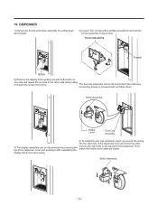
... solenoid switch. Motor Assembly Holder Lever Duct Cap Assembly 6) To install the duct cap assembly, insert one side and repeat the process in the top part of the dispenser cover and pushing it forward like shows the picture. 10. Motor Assembly - 19 - DISPENSER 1) Disconnect funnel and button assembly by pressing the...
... solenoid switch. Motor Assembly Holder Lever Duct Cap Assembly 6) To install the duct cap assembly, insert one side and repeat the process in the top part of the dispenser cover and pushing it forward like shows the picture. 10. Motor Assembly - 19 - DISPENSER 1) Disconnect funnel and button assembly by pressing the...
Owner's Manual
Page 21
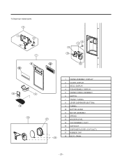
7) Dispenser related parts 5 7 6 8 12 16 11 13 18 10 9 18 14 17 15 1 FRAME ASSEMBLY, DISPLAY 2 COVER, DISPLAY 3 DECO, DISPLAY 4 PCB ASSEMBLY, DISPLAY 5 FRAME FUNNEL ASSEMBLY 6 SWITCH 7 FRAME, FUNNEL 8 LEVER DISPENSER (BUTTON) 9 FUNNEL 10 BUTTON LEVER 11 MOTOR ASSEMBLY 12 SPRING 13 HOLDER LEVEL 14 CAP ASSEMBLY, DUCT 15 CAP, DUCT 16 DISPENSER LEVER, (CAP DUCT) 17 RUBBER, CAP 18 DECO, DRAIN - 20 -
7) Dispenser related parts 5 7 6 8 12 16 11 13 18 10 9 18 14 17 15 1 FRAME ASSEMBLY, DISPLAY 2 COVER, DISPLAY 3 DECO, DISPLAY 4 PCB ASSEMBLY, DISPLAY 5 FRAME FUNNEL ASSEMBLY 6 SWITCH 7 FRAME, FUNNEL 8 LEVER DISPENSER (BUTTON) 9 FUNNEL 10 BUTTON LEVER 11 MOTOR ASSEMBLY 12 SPRING 13 HOLDER LEVEL 14 CAP ASSEMBLY, DUCT 15 CAP, DUCT 16 DISPENSER LEVER, (CAP DUCT) 17 RUBBER, CAP 18 DECO, DRAIN - 20 -

Owner's Manual
Page 26
... are opened. 2) For initial power on and off by how often and how long the dorrs are sequentially operated as follows to prevent noise and part damage from TEST MODE to the defect diagnosis function, 8-1-15). 4) Defrosting won 't be performed. When Defrost Sensor is repeated and completed in case of On...
... are opened. 2) For initial power on and off by how often and how long the dorrs are sequentially operated as follows to prevent noise and part damage from TEST MODE to the defect diagnosis function, 8-1-15). 4) Defrosting won 't be performed. When Defrost Sensor is repeated and completed in case of On...
Owner's Manual
Page 29
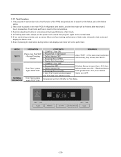
... 2 NORMAL OPERATION OPERATION Press once Test S/W From Test 1 press again TEST S/W From Test 2 press again TEST S/W CONTENTS 1. Freezer fan in it again for the failure part at the failure status. 2. Stepping Motor CLOSE 5. Only F & R notch are found during performance of test mode. 4. COMP & C Fan ON 2. Display fully illuminated 1. If Defrost Sensor...
... 2 NORMAL OPERATION OPERATION Press once Test S/W From Test 1 press again TEST S/W From Test 2 press again TEST S/W CONTENTS 1. Freezer fan in it again for the failure part at the failure status. 2. Stepping Motor CLOSE 5. Only F & R notch are found during performance of test mode. 4. COMP & C Fan ON 2. Display fully illuminated 1. If Defrost Sensor...
Owner's Manual
Page 31
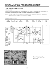
... MICOM CIRCUIT 1. Caution : Since high voltage (160 Vdc) is as follows: Parte VAVA11 VVolttaajgee 11101~01~21727VVac CCEE11 161060VVdcdc CCEE22 1414VVdcdc CCEE33 1212VVdcdc CCEE44 151.55.5VVdcdc CCEE5 5 5 5VVdcdc The part highlighted, are the components of a rectifier (BD1 and CE1) converting AC to dissipate.... It consists of the Switched Mode Power Supply - 30 - Voltage of every part is maintained at the power terminal, wait at least 3 minutes after unplugging the appliance to check the voltages to allow the current to...
... MICOM CIRCUIT 1. Caution : Since high voltage (160 Vdc) is as follows: Parte VAVA11 VVolttaajgee 11101~01~21727VVac CCEE11 161060VVdcdc CCEE22 1414VVdcdc CCEE33 1212VVdcdc CCEE44 151.55.5VVdcdc CCEE5 5 5 5VVdcdc The part highlighted, are the components of a rectifier (BD1 and CE1) converting AC to dissipate.... It consists of the Switched Mode Power Supply - 30 - Voltage of every part is maintained at the power terminal, wait at least 3 minutes after unplugging the appliance to check the voltages to allow the current to...
Owner's Manual
Page 32
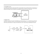
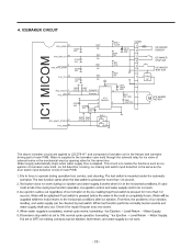
.... CSTLS4M00G53-A0 0SCI 2 XIN IC1 R14* IM MICOM XOUT 3 1-3. Reset circuit The RESET circuit allows various parts of the MICOM will not operate. The oscillator (OSC1) must always be replaced with an exact rated part, because if this changes, the time calculations of the MICOM, such as RAM, defrosting, etc., to reset...
.... CSTLS4M00G53-A0 0SCI 2 XIN IC1 R14* IM MICOM XOUT 3 1-3. Reset circuit The RESET circuit allows various parts of the MICOM will not operate. The oscillator (OSC1) must always be replaced with an exact rated part, because if this changes, the time calculations of the MICOM, such as RAM, defrosting, etc., to reset...
Owner's Manual
Page 33
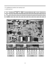
... 3 CON 4 PIN 9 PIN 5 115 ~ 127 VAC + - CON 1 CON 1 PIN 1 PIN 7 115 ~ 127 VAC 115 ~ 127 VAC 0 VAC 0 VAC DEFROST HEATER + - Load Driving Circuit LOAD MEASURING PART ON STATUS OFF COMPRESSOR + - 1-4. Load/dispenser operation, door opening circuit 1. CON 2 CON 2 PIN 9 PIN 3 115 ~ 127 VAC + CON 3 PIN 5 CON 4 PIN 5 115 ~ 127 VAC 0 VAC...
... 3 CON 4 PIN 9 PIN 5 115 ~ 127 VAC + - CON 1 CON 1 PIN 1 PIN 7 115 ~ 127 VAC 115 ~ 127 VAC 0 VAC 0 VAC DEFROST HEATER + - Load Driving Circuit LOAD MEASURING PART ON STATUS OFF COMPRESSOR + - 1-4. Load/dispenser operation, door opening circuit 1. CON 2 CON 2 PIN 9 PIN 3 115 ~ 127 VAC + CON 3 PIN 5 CON 4 PIN 5 115 ~ 127 VAC 0 VAC...
Owner's Manual
Page 35
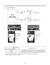
B , C - B , C - D . DOOR S/W BO, PK PIN 3&4 Measuring Part Door of Freezer / Refrigerator Closing Opening IC1 (MICOM) PIN 39, 40 5 V ( A - D . Interruptor en ambos extremos están encendidos) • Since door switches (A) and (B) are interconnected, ...
B , C - B , C - D . DOOR S/W BO, PK PIN 3&4 Measuring Part Door of Freezer / Refrigerator Closing Opening IC1 (MICOM) PIN 39, 40 5 V ( A - D . Interruptor en ambos extremos están encendidos) • Since door switches (A) and (B) are interconnected, ...
Owner's Manual
Page 41
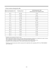
... k 60 k 47.3 k 38.4 k 30 k? 24.1 k 19.5 k 15.9 k 13 k? 11 k 8.9 k 6.2 k 4.3 k • Resistance value allowance of sensor is necessary because of the PWB ASSEMBLY and the MAIN part. - 40 - An analog tester has to stabilize for at least 3 minutes before measuring. This delay is ±5%. • When measuring the resistance value of the...
... k 60 k 47.3 k 38.4 k 30 k? 24.1 k 19.5 k 15.9 k 13 k? 11 k 8.9 k 6.2 k 4.3 k • Resistance value allowance of sensor is necessary because of the PWB ASSEMBLY and the MAIN part. - 40 - An analog tester has to stabilize for at least 3 minutes before measuring. This delay is ±5%. • When measuring the resistance value of the...
Owner's Manual
Page 51
... 28 R25* R24* 4.7K 4.7K SW 2 2 1 The above icemaker circuits are applied to LSC27914** and composed of icemaker unit in the freezer and icemaker driving part of solenoid valve in the mechanical area by opening valve for ice valve of main PWB.
... 28 R25* R24* 4.7K 4.7K SW 2 2 1 The above icemaker circuits are applied to LSC27914** and composed of icemaker unit in the freezer and icemaker driving part of solenoid valve in the mechanical area by opening valve for ice valve of main PWB.
Owner's Manual
Page 52
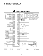
CIRCUIT DIAGRAM CIRCUIT DIAGRAM ICE MAKER UNIT M I/M MOTOR HALL IC I/M TEST S/W S/W ICE MAKER PART STOP S/W I/M SENSOR STEPPING MOTOR R2-SENSOR R1-SENSOR R-DOOR a PERCEPTION S/W b DAMPER-HTR PWB ASSEMBLY, DISPLAY M DUCT MOTOR SB 11 YL 10...COMP' 3 4 6 * COMP' ACCESSORIES CR BL N BK L OLP C-FAN 52 5 2 2 5 PTC COMBO KIT (PTC+OLP) c F-DOOR d PERCEPTION S/W D-SENSOR F-SENSOR * PLUG TYPE, CAPACITOR PART, P.T.C, FUSE-M AND COMP' ACCESSORIES ON CIRCUIT DIAGRAM ARE SUBJECT TO CHANGE IN DIFFERENT LOCALITIES AND MODEL TYPE. SOLENOID CUBE FUSE-M SHEATH-HTR 115V/60Hz DISPENSER...
CIRCUIT DIAGRAM CIRCUIT DIAGRAM ICE MAKER UNIT M I/M MOTOR HALL IC I/M TEST S/W S/W ICE MAKER PART STOP S/W I/M SENSOR STEPPING MOTOR R2-SENSOR R1-SENSOR R-DOOR a PERCEPTION S/W b DAMPER-HTR PWB ASSEMBLY, DISPLAY M DUCT MOTOR SB 11 YL 10...COMP' 3 4 6 * COMP' ACCESSORIES CR BL N BK L OLP C-FAN 52 5 2 2 5 PTC COMBO KIT (PTC+OLP) c F-DOOR d PERCEPTION S/W D-SENSOR F-SENSOR * PLUG TYPE, CAPACITOR PART, P.T.C, FUSE-M AND COMP' ACCESSORIES ON CIRCUIT DIAGRAM ARE SUBJECT TO CHANGE IN DIFFERENT LOCALITIES AND MODEL TYPE. SOLENOID CUBE FUSE-M SHEATH-HTR 115V/60Hz DISPENSER...
Owner's Manual
Page 55
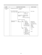
...HOW TO CHECK 2) Poor defrosting capacity. Other foreign materials input. Dent by a screw or clamp. CAUSES AND CHECK POINTS. 1) Refrigerant Partly leaked. Parts leak. Damage by fin evaporator. P=Power V=Voltage Wire is not cut . Seal with drain. • Check visually. CLAIMS. 3. If... cut , refer to resistance. Weld joint leak. Drain path (pipe) clogged. Defrost heater does not generate heat. Heating wire. Parts Plate disconnected. Heating wire. - Contact point between heating and electric wire. Lead wire. - Refrigeration is cut. - Inject adiabatics ...
...HOW TO CHECK 2) Poor defrosting capacity. Other foreign materials input. Dent by a screw or clamp. CAUSES AND CHECK POINTS. 1) Refrigerant Partly leaked. Parts leak. Damage by fin evaporator. P=Power V=Voltage Wire is not cut . Seal with drain. • Check visually. CLAIMS. 3. If... cut , refer to resistance. Weld joint leak. Drain path (pipe) clogged. Defrost heater does not generate heat. Heating wire. Parts Plate disconnected. Heating wire. - Contact point between heating and electric wire. Lead wire. - Refrigeration is cut. - Inject adiabatics ...
Owner's Manual
Page 57
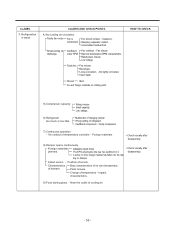
... Damping evaporator contact. Small cooling air discharge. Fan misuse. Low voltage. Fan misuse. Not tightly connected. Bent. Ice and foreign materials on rotating parts. Rating misuse. Low valtage. 6) Refrigerant too much or too little. Malfunction of damper. Insufficient compressor. - Faulty compressor. 7) Continuous operation - ...A screw or other foreign material has fallen into the drip tray or damper. Characteristics of charging cylinder. Parts misuse. Charge of cooling air. - 56 - Impact. Near the outlet of temperature -
... Damping evaporator contact. Small cooling air discharge. Fan misuse. Low voltage. Fan misuse. Not tightly connected. Bent. Ice and foreign materials on rotating parts. Rating misuse. Low valtage. 6) Refrigerant too much or too little. Malfunction of damper. Insufficient compressor. - Faulty compressor. 7) Continuous operation - ...A screw or other foreign material has fallen into the drip tray or damper. Characteristics of charging cylinder. Parts misuse. Charge of cooling air. - 56 - Impact. Near the outlet of temperature -


