Owner's Manual
Page 3
Door Alignment...6 2. Removing and Replacing Refrigerator door 11 2. Fan Shroud Grille...14 5. MICOM FUNCTION ...21 1. Explanation for PCB circuit 30 7. TROUBLE DIAGNOSIS...54 10. SPECIFICATIONS ...4 2. PARTS IDENTIFICATION ...5 3. Refrigerator Shelves...8 4. Freezer Shelf...8 5. How to ice maker 9 4. EXPLODED VIEW ...132 - 2 - Install Water Filter...7 3. Monitor Panel...21 6. Function on Icemaker...46 3. Handle Removal...ICEMAKER AND DISPENSER WORKING PRINCIPLES AND REPAIR 45 1. How to Control the amount of water supplied to Remove Swtich Lamp 13 4.
Door Alignment...6 2. Removing and Replacing Refrigerator door 11 2. Fan Shroud Grille...14 5. MICOM FUNCTION ...21 1. Explanation for PCB circuit 30 7. TROUBLE DIAGNOSIS...54 10. SPECIFICATIONS ...4 2. PARTS IDENTIFICATION ...5 3. Refrigerator Shelves...8 4. Freezer Shelf...8 5. How to ice maker 9 4. EXPLODED VIEW ...132 - 2 - Install Water Filter...7 3. Monitor Panel...21 6. Function on Icemaker...46 3. Handle Removal...ICEMAKER AND DISPENSER WORKING PRINCIPLES AND REPAIR 45 1. How to Control the amount of water supplied to Remove Swtich Lamp 13 4.
Owner's Manual
Page 7
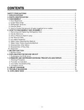
...doors, remove the Base Grille. Tools you need • Wrench 5/16 in (8 mm) • Wrench 3/4 in (19 mm) Left leveling leg Height difference Height difference Height difference Keeper nut Wrench Height Adjustment Up difference hinge pin Down If the freezer compartment door is lower than the refrigerator compartment door... ½" (1.27 cm)). If the freezer compartment door is higher than the freezer door during the installation of the left leveling leg and rotating it clockwise. AFTER LEVELING THE DOOR HEIGHT Make sure the front leveling legs are completely touching...
...doors, remove the Base Grille. Tools you need • Wrench 5/16 in (8 mm) • Wrench 3/4 in (19 mm) Left leveling leg Height difference Height difference Height difference Keeper nut Wrench Height Adjustment Up difference hinge pin Down If the freezer compartment door is lower than the refrigerator compartment door... ½" (1.27 cm)). If the freezer compartment door is higher than the freezer door during the installation of the left leveling leg and rotating it clockwise. AFTER LEVELING THE DOOR HEIGHT Make sure the front leveling legs are completely touching...
Owner's Manual
Page 8
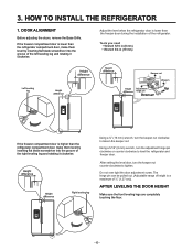
... receptacle. Replace the shelf to purge the system, depressing and releasing the dispenser button (30 seconds ON, 60 seconds OFF). Open the refrigerator door and check the shelf area for the future. Turn on , you have to lock it down . The substitute cap must be lined up ...with the indicator arrow. Press the Filter button for 3 seconds to turn clockwise to change the water filter. Before removing or installing water filter: 1. 2. INSTALL WATER FILTER • Filter Reset: When the Filter icon turns on household water supply. 3. IMPORTANT: Turn off...
... receptacle. Replace the shelf to purge the system, depressing and releasing the dispenser button (30 seconds ON, 60 seconds OFF). Open the refrigerator door and check the shelf area for the future. Turn on , you have to lock it down . The substitute cap must be lined up ...with the indicator arrow. Press the Filter button for 3 seconds to turn clockwise to change the water filter. Before removing or installing water filter: 1. 2. INSTALL WATER FILTER • Filter Reset: When the Filter icon turns on household water supply. 3. IMPORTANT: Turn off...
Owner's Manual
Page 12
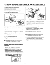
... is the same. 4. Lift up the cover. 3.Rotate the hinge lever (3) clockwise. NOTE: Regardless of the latch, be careful that the door does not fall forward. 6. REMOVING AND REPLACING REFRIGERATOR DOORS Before removing the doors, remove the base grille. Remove the top hinge cover screw (1). 2. Lift the top hinge (6) free of the hinge lever latch (5). Place the...
... is the same. 4. Lift up the cover. 3.Rotate the hinge lever (3) clockwise. NOTE: Regardless of the latch, be careful that the door does not fall forward. 6. REMOVING AND REPLACING REFRIGERATOR DOORS Before removing the doors, remove the base grille. Remove the top hinge cover screw (1). 2. Lift the top hinge (6) free of the hinge lever latch (5). Place the...
Owner's Manual
Page 13
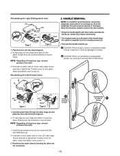
... keyhole slots (2) on the back of hinge lever type, removal process is the same. 3. removal process is the same. 3. Position cover (2) into place. HANDLE REMOVAL NOTE: It is necessary to remove the refrigerator doors when it could be damaged or broken. Position cover into ...place. Fit top hinge (4) over hinge lever latch (7) and into place. Rotate lever (3) counterclockwise to remove the door handles. • Grasp the handle tigthtly with moment force. (2) (1) (4) (5) (6) (7) Type 1 (3) (7) (5) (6) Rivet Type 2 Screws ...
... keyhole slots (2) on the back of hinge lever type, removal process is the same. 3. removal process is the same. 3. Position cover (2) into place. HANDLE REMOVAL NOTE: It is necessary to remove the refrigerator doors when it could be damaged or broken. Position cover into ...place. Fit top hinge (4) over hinge lever latch (7) and into place. Rotate lever (3) counterclockwise to remove the door handles. • Grasp the handle tigthtly with moment force. (2) (1) (4) (5) (6) (7) Type 1 (3) (7) (5) (6) Rivet Type 2 Screws ...
Owner's Manual
Page 14
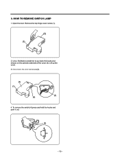
Use a flat blade screwdriver to pry back the hooks (not shown) on the cabinet underside of the cover (2). Open the door. Lift up the cover. 3. Disconnect the wire harnesses(3). (2) (1) (3) (4) 4. To remove the switch (4) press and hold the hooks and push it out. (4) - 13 - Remove the top hinge cover screw (1). (2) (1) 2. HOW TO REMOVE SWITCH LAMP 1. 3.
Use a flat blade screwdriver to pry back the hooks (not shown) on the cabinet underside of the cover (2). Open the door. Lift up the cover. 3. Disconnect the wire harnesses(3). (2) (1) (3) (4) 4. To remove the switch (4) press and hold the hooks and push it out. (4) - 13 - Remove the top hinge cover screw (1). (2) (1) 2. HOW TO REMOVE SWITCH LAMP 1. 3.

Owner's Manual
Page 26
... MODE 2 TEST SW (PRESS Once) OTHER LOADS OFF 0.6 sec. 0.3 sec. When Defrost Sensor is a load movement sequence in the cycle of F/R doors closed. ON 10 15 DEF HTR sec. F-FAN Hi-Speed & 0.3 sec. If pressing S/W once more than 5°C, it has been on and off... stops if the sensor tempreature reaches 41°F (5°C) or more than 5°C TEST SW (PRESS 2 Times) 0.3 sec. 0.6 sec. Defrosting (Removing frost) 1) Defrosting starts each time the accumulated COMPRESSOR runnig time is more . C-FAN ON DAMPER OPEN COMP ON In case of Defrost Sensor is determinated...
... MODE 2 TEST SW (PRESS Once) OTHER LOADS OFF 0.6 sec. 0.3 sec. When Defrost Sensor is a load movement sequence in the cycle of F/R doors closed. ON 10 15 DEF HTR sec. F-FAN Hi-Speed & 0.3 sec. If pressing S/W once more than 5°C, it has been on and off... stops if the sensor tempreature reaches 41°F (5°C) or more than 5°C TEST SW (PRESS 2 Times) 0.3 sec. 0.6 sec. Defrosting (Removing frost) 1) Defrosting starts each time the accumulated COMPRESSOR runnig time is more . C-FAN ON DAMPER OPEN COMP ON In case of Defrost Sensor is determinated...
Owner's Manual
Page 64
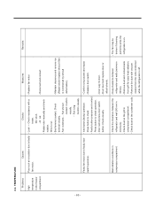
... (minimum minimum). 50mm). - Wire is off. - Fan icing: Confirm visually. - Faulty fan motor due to check - Door liner bent:replace door or attach sheets. Fan constraint. - Press button to faulty door switch operation. - Maintain clearance and remove ice (Repair and/or replace shroud if fan is on. Bad radiation conditions in the freezer compartment...
... (minimum minimum). 50mm). - Wire is off. - Fan icing: Confirm visually. - Faulty fan motor due to check - Door liner bent:replace door or attach sheets. Fan constraint. - Press button to faulty door switch operation. - Maintain clearance and remove ice (Repair and/or replace shroud if fan is on. Bad radiation conditions in the freezer compartment...
Owner's Manual
Page 87
CHECKING FLOW 1 Check the Door Gasket for any abnormality. 7) Abnormal Defrost Error NO. Unplug the product, remove Grille Fan assy, and check the Defrost Control Part. 2 Defrost Controller Assy connector Defrost sensor Defrost Heater Connector Fuse-M Reset Refrigerator, then, enter to TEST ...
CHECKING FLOW 1 Check the Door Gasket for any abnormality. 7) Abnormal Defrost Error NO. Unplug the product, remove Grille Fan assy, and check the Defrost Control Part. 2 Defrost Controller Assy connector Defrost sensor Defrost Heater Connector Fuse-M Reset Refrigerator, then, enter to TEST ...
Owner's Manual
Page 96
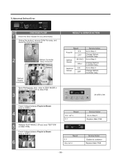
CHECKING FLOW Remove Cover hinge in Freezer Door, and check connection. 8 RESULT & SERVICE ACTION Result Firmly plugged Loose Service Action Go to Step 9 Disconnect joint 1 as is not working NO. Result 0 Ù OFF Service Action Replace Door assembly Explain to Step 10 10 Unplug connector from Duct Motor and check the resistance value in the picture. 9 Then check resistance value marked points. Result 0 Ù OFF Service Action Replace Product Go to customer - 95 - 11) Ice Cube Mode is marked in the connector.
CHECKING FLOW Remove Cover hinge in Freezer Door, and check connection. 8 RESULT & SERVICE ACTION Result Firmly plugged Loose Service Action Go to Step 9 Disconnect joint 1 as is not working NO. Result 0 Ù OFF Service Action Replace Door assembly Explain to Step 10 10 Unplug connector from Duct Motor and check the resistance value in the picture. 9 Then check resistance value marked points. Result 0 Ù OFF Service Action Replace Product Go to customer - 95 - 11) Ice Cube Mode is marked in the connector.
Owner's Manual
Page 98
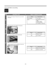
... Other Service Action Go to Step 7 Change PCB Not Pressing Same than Go to Step 7 pressing voltage, but inverted Other Change PCB -12V Remove Cover hinge in Freezer Door, and check connection. 7 Result Firmly plugged Loose Service Action Go to 3 Other Replace Duct Motor Check Duct Motor signal in CON 9. CHECKING FLOW...
... Other Service Action Go to Step 7 Change PCB Not Pressing Same than Go to Step 7 pressing voltage, but inverted Other Change PCB -12V Remove Cover hinge in Freezer Door, and check connection. 7 Result Firmly plugged Loose Service Action Go to 3 Other Replace Duct Motor Check Duct Motor signal in CON 9. CHECKING FLOW...
Owner's Manual
Page 102
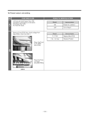
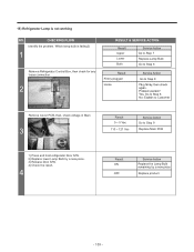
CHECKING FLOW 1) Press and hold Freezer Door S/W. 2) Replace Lamp Bulb by a new piece. 5 3) Release Door S/W. 4) Check the result. Remove Cover PCB, then, check voltage from Main PCB in blue wire (NEUTRAL) - 101 - 14) Freezer Lamp is not working NO. Place Test Point (+) in yellow wire (LIVE) 6 CON 3 RESULT & SERVICE ACTION Result ON OFF Service Action Explain to customer Go to Step 6 Result 0 ~ 5 Vac 110 ~ 127 Vac Service Action Replace Main PCB Replace Product CON 2 Place Test Point (-) in CON 2 & CON 3.
CHECKING FLOW 1) Press and hold Freezer Door S/W. 2) Replace Lamp Bulb by a new piece. 5 3) Release Door S/W. 4) Check the result. Remove Cover PCB, then, check voltage from Main PCB in blue wire (NEUTRAL) - 101 - 14) Freezer Lamp is not working NO. Place Test Point (+) in yellow wire (LIVE) 6 CON 3 RESULT & SERVICE ACTION Result ON OFF Service Action Explain to customer Go to Step 6 Result 0 ~ 5 Vac 110 ~ 127 Vac Service Action Replace Main PCB Replace Product CON 2 Place Test Point (-) in CON 2 & CON 3.
Owner's Manual
Page 104
... Upper Lower Both Service Action Go to Step 7 Replace Lamp Bulb Go to Step 8 Result Firmly plugged Loose Service Action Go to Step 8 Remove Cover PCB, then, check voltage in Main 3 Result 0 ~ 5 Vac 110 ~ 127 Vac Service Action Go to Step 9 Replace Main PCB 1) ...Press and hold refrigerator Door S/W. 2) Replace lower Lamp Bulb by a new piece. 3) Release Door S/W. 4) Check the result. 4 Result ON OFF Service Action Replace the Lamp Bulb remaining by a new piece Replace product - 103 -
... Upper Lower Both Service Action Go to Step 7 Replace Lamp Bulb Go to Step 8 Result Firmly plugged Loose Service Action Go to Step 8 Remove Cover PCB, then, check voltage in Main 3 Result 0 ~ 5 Vac 110 ~ 127 Vac Service Action Go to Step 9 Replace Main PCB 1) ...Press and hold refrigerator Door S/W. 2) Replace lower Lamp Bulb by a new piece. 3) Release Door S/W. 4) Check the result. 4 Result ON OFF Service Action Replace the Lamp Bulb remaining by a new piece Replace product - 103 -
Owner's Manual
Page 111
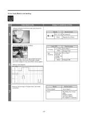
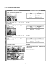
... 10 Go to TEST MODE 2 (Press once the TEST S/W in Main PCB). 1) Open Refrigerator door. 2) Press manually the refrigerator door S/W. 5 3) Check the air flow. 6 Turn Off the refrigerator. 1) Remove Control Box in Main PCB). 1) Open Refrigerator door. 2) Press manually the refrigerator door S/W, wait 10 seconds. 3) Check the air flow. 3 Go to Step 3 Result Air flow...
... 10 Go to TEST MODE 2 (Press once the TEST S/W in Main PCB). 1) Open Refrigerator door. 2) Press manually the refrigerator door S/W. 5 3) Check the air flow. 6 Turn Off the refrigerator. 1) Remove Control Box in Main PCB). 1) Open Refrigerator door. 2) Press manually the refrigerator door S/W, wait 10 seconds. 3) Check the air flow. 3 Go to Step 3 Result Air flow...

Owner's Manual
Page 114
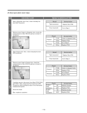
20) Refrigerator apparently doesn't work NO. Remove Cover PCB, then, check voltage in CON 201 as is shown in the picture. 4 RESULT & SERVICE ACTION Result YES NO Service Action Go to Step 2 ... Action Go to Step 6 Replace Main PCB - 113 - CHECKING FLOW Lamps are working? 1 Refrigerator and Freezer notch indicator are in OFF position? 2 Open the refrigerator door, then, in the picture.
20) Refrigerator apparently doesn't work NO. Remove Cover PCB, then, check voltage in CON 201 as is shown in the picture. 4 RESULT & SERVICE ACTION Result YES NO Service Action Go to Step 2 ... Action Go to Step 6 Replace Main PCB - 113 - CHECKING FLOW Lamps are working? 1 Refrigerator and Freezer notch indicator are in OFF position? 2 Open the refrigerator door, then, in the picture.
Owner's Manual
Page 116
...Replace product Replace PCB - 115 - Check the result. 21) Door open alarm never stops NO. CHECKING FLOW Open refrigerator door, then, check manually the door S/W movement. 1 Remove cover hinge in refrigerator door, check the measurement in Door S/W DC part as is shown in the picture. 2 RESULT &...Service Action Check in released mode Replace PCB Go to Step 3 Replace PCB Open freezer door, then, check manually the door S/W movement. 3 Remove cover hinge in freezer door, check the measurement in Door S/W DC part as is shown in the picture. 4 Result Tight movement Free movement ...
...Replace product Replace PCB - 115 - Check the result. 21) Door open alarm never stops NO. CHECKING FLOW Open refrigerator door, then, check manually the door S/W movement. 1 Remove cover hinge in refrigerator door, check the measurement in Door S/W DC part as is shown in the picture. 2 RESULT &...Service Action Check in released mode Replace PCB Go to Step 3 Replace PCB Open freezer door, then, check manually the door S/W movement. 3 Remove cover hinge in freezer door, check the measurement in Door S/W DC part as is shown in the picture. 4 Result Tight movement Free movement ...


