Owner's Manual
Page 3
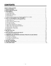
PARTS IDENTIFICATION ...5 3. Removing and Replacing Refrigerator door 11 2. Water Valve Disassembly Method 15 7. Install Water Filter...7 3. Handle Removal...12 3. Disassemble of Tray Drip 18 10. Disassemble of fan Motor 17 9. Monitor Panel...21... Shelves...8 4. HOW TO DISASSEMBLY AND ASSEMBLY 11 1. Dispenser...19 5. Function on Icemaker...46 3. CONTENTS SAFETY PRECAUTIONS ...3 1. Door Alignment...6 2. How to ice maker 9 4. ICEMAKER AND DISPENSER WORKING PRINCIPLES AND REPAIR 45 1. EXPLANATION FOR MICOM CIRCUIT 30 1. DISASSEMBLY ...6 1.
PARTS IDENTIFICATION ...5 3. Removing and Replacing Refrigerator door 11 2. Water Valve Disassembly Method 15 7. Install Water Filter...7 3. Handle Removal...12 3. Disassemble of Tray Drip 18 10. Disassemble of fan Motor 17 9. Monitor Panel...21... Shelves...8 4. HOW TO DISASSEMBLY AND ASSEMBLY 11 1. Dispenser...19 5. Function on Icemaker...46 3. CONTENTS SAFETY PRECAUTIONS ...3 1. Door Alignment...6 2. How to ice maker 9 4. ICEMAKER AND DISPENSER WORKING PRINCIPLES AND REPAIR 45 1. EXPLANATION FOR MICOM CIRCUIT 30 1. DISASSEMBLY ...6 1.
Owner's Manual
Page 5
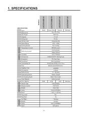
... LSC27914SW /01 LSC27914TT /01 LSC27914ST /01 FREEZER REFRIGERATOR SPECIFICATIONS Color Dimensions Net Weight Capacity Refrigerant Climate class Rated Rating Cooling System Temperature Control Defrosting System Insulation Compressor Evaporator Condenser Lubricanting Oil Drier Capillary Tube First Defrost Defrost Cycle Desfrosting Device Anti-freezing Heater Case Material Door Material Handle Type Display Graphic Basket Lamp...
... LSC27914SW /01 LSC27914TT /01 LSC27914ST /01 FREEZER REFRIGERATOR SPECIFICATIONS Color Dimensions Net Weight Capacity Refrigerant Climate class Rated Rating Cooling System Temperature Control Defrosting System Insulation Compressor Evaporator Condenser Lubricanting Oil Drier Capillary Tube First Defrost Defrost Cycle Desfrosting Device Anti-freezing Heater Case Material Door Material Handle Type Display Graphic Basket Lamp...
Owner's Manual
Page 13
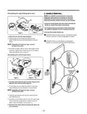
... (1) (this may require some force). • The keyhole slots (2) on the back of the handle allow the handle to remove the door handles. • Grasp the handle tigthtly with moment force. (2) (1) (4) (5) (6) (7) Type 1 (3) (7) (5) (6) Rivet Type 2 Screws mounted on door switch side of cover (2) under edge of wire opening . Rotate lever (5) clockwise to secure hinge. Insert and tighten...
... (1) (this may require some force). • The keyhole slots (2) on the back of the handle allow the handle to remove the door handles. • Grasp the handle tigthtly with moment force. (2) (1) (4) (5) (6) (7) Type 1 (3) (7) (5) (6) Rivet Type 2 Screws mounted on door switch side of cover (2) under edge of wire opening . Rotate lever (5) clockwise to secure hinge. Insert and tighten...


