Owner's Manual
Page 3
DISASSEMBLY ...6 1. Freezer Shelf...8 5. How to Control the amount of water supplied to Remove Swtich Lamp 13 4. How to ice maker 9 4. Dispenser...19 5. Explanation for PCB circuit 30 7. EXPLODED VIEW ...132 ... of fan Motor 17 9. Working Principles...45 2. SPECIFICATIONS ...4 2. Fan Shroud Grille...14 5. Water Valve Tubes Assembly Method 16 8. MICOM FUNCTION ...21 1. TROUBLE DIAGNOSIS...54 10. Icemaker Circuit...50 8. Install Water Filter...7 3. Water Valve Disassembly Method 15 7. CIRCUIT DIAGRAM...51 9. EXPLANATION FOR MICOM CIRCUIT 30 1. Function on ...
DISASSEMBLY ...6 1. Freezer Shelf...8 5. How to Control the amount of water supplied to Remove Swtich Lamp 13 4. How to ice maker 9 4. Dispenser...19 5. Explanation for PCB circuit 30 7. EXPLODED VIEW ...132 ... of fan Motor 17 9. Working Principles...45 2. SPECIFICATIONS ...4 2. Fan Shroud Grille...14 5. Water Valve Tubes Assembly Method 16 8. MICOM FUNCTION ...21 1. TROUBLE DIAGNOSIS...54 10. Icemaker Circuit...50 8. Install Water Filter...7 3. Water Valve Disassembly Method 15 7. CIRCUIT DIAGRAM...51 9. EXPLANATION FOR MICOM CIRCUIT 30 1. Function on ...

Owner's Manual
Page 4
... may cause frost bite. 9.Service on the refrigerator should be performed by a qualified technician.Sealed system repair must be performed by a CFC certified technician. 6.Prevent water from spiling on to electric elements or the machine parts. - 3 -
... may cause frost bite. 9.Service on the refrigerator should be performed by a qualified technician.Sealed system repair must be performed by a CFC certified technician. 6.Prevent water from spiling on to electric elements or the machine parts. - 3 -
Owner's Manual
Page 5
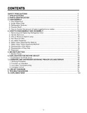
1. SPECIFICATIONS GENERAL FEATURES MODELS LSC27914SB /01 LSC27914SW /01 LSC27914TT /01 LSC27914ST /01 FREEZER REFRIGERATOR SPECIFICATIONS Color Dimensions Net Weight Capacity Refrigerant Climate class Rated Rating Cooling System Temperature Control Defrosting System Insulation Compressor... Type Fin Tube Type Wire Condenser Polyol Ester (POE) 310 ± 10 cc MOLECULAR SIEVE XH-7 ID Ø0.80 4 Hours 13 - 70 Hours Heater, Sheath Water Tank Heater Embo (normal) PCM VCM Vista (plastic) ICE PLUS 3full+1half Yes (2) 40W/Blue 1 (Fix) + 2 (S/Out) Yes No Twisting 4 plastic Yes ...
1. SPECIFICATIONS GENERAL FEATURES MODELS LSC27914SB /01 LSC27914SW /01 LSC27914TT /01 LSC27914ST /01 FREEZER REFRIGERATOR SPECIFICATIONS Color Dimensions Net Weight Capacity Refrigerant Climate class Rated Rating Cooling System Temperature Control Defrosting System Insulation Compressor... Type Fin Tube Type Wire Condenser Polyol Ester (POE) 310 ± 10 cc MOLECULAR SIEVE XH-7 ID Ø0.80 4 Hours 13 - 70 Hours Heater, Sheath Water Tank Heater Embo (normal) PCM VCM Vista (plastic) ICE PLUS 3full+1half Yes (2) 40W/Blue 1 (Fix) + 2 (S/Out) Yes No Twisting 4 plastic Yes ...
Owner's Manual
Page 6
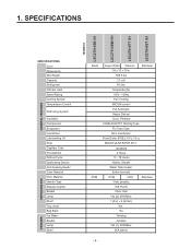
... or fresh food. 2. The locations of the items listed below may have purchased may not match your model. L Refrigerator Door Rack M Vegetable Drawer - 5 - PARTS IDENTIFICATION G A H B I Water Filter J Refrigerator Shelf K Snack Pan For storage of dairy products such as butter and cheese. H Refrigerator Lamp I C J K D H L A E A M L F Use this page to the dispenser. A Freezer Door...
... or fresh food. 2. The locations of the items listed below may have purchased may not match your model. L Refrigerator Door Rack M Vegetable Drawer - 5 - PARTS IDENTIFICATION G A H B I Water Filter J Refrigerator Shelf K Snack Pan For storage of dairy products such as butter and cheese. H Refrigerator Lamp I C J K D H L A E A M L F Use this page to the dispenser. A Freezer Door...
Owner's Manual
Page 8
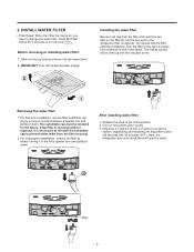
... 7 - Turn the filter to the right a quarter turn the icon . Press the Filter button for 3 seconds to change the water filter. For subsequent installation, remove old filter by turning it counterclockwise a quarter turn and pulling it into the two slots in the ... dispenser button (30 seconds ON, 60 seconds OFF). IMPORTANT: Turn off household water supply. For first-time installation, remove filter substitute cap (A) by slowly turning it down . Dispense 2.5 gallons (9.46 L) of water to the initial position. 2. Open the refrigerator door and check the shelf area...
... 7 - Turn the filter to the right a quarter turn the icon . Press the Filter button for 3 seconds to change the water filter. For subsequent installation, remove old filter by turning it counterclockwise a quarter turn and pulling it into the two slots in the ... dispenser button (30 seconds ON, 60 seconds OFF). IMPORTANT: Turn off household water supply. For first-time installation, remove filter substitute cap (A) by slowly turning it down . Dispense 2.5 gallons (9.46 L) of water to the initial position. 2. Open the refrigerator door and check the shelf area...
Owner's Manual
Page 10
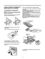
... goes into the auger drive … . Make sure it . Feeler Arm Test switch (On the lower part of icemaker) 2 1 * It is acceptable is the adjusted water level is small each time. 5. NOTE: Use both hands to remove the ice bin to the drawing below . 1. and pull it out while slightly lifting..., follow these steps: • Lift the ice shelf as shown in it „ . HOW TO CONTROL THE AMOUNT OF 2) Turn on the electricity after connecting water pipe. WATER SUPPLIED TO ICE MAKER 1) Press the test switch under the ice tray and press test switch. 4) When the ice tray rotates, the...
... goes into the auger drive … . Make sure it . Feeler Arm Test switch (On the lower part of icemaker) 2 1 * It is acceptable is the adjusted water level is small each time. 5. NOTE: Use both hands to remove the ice bin to the drawing below . 1. and pull it out while slightly lifting..., follow these steps: • Lift the ice shelf as shown in it „ . HOW TO CONTROL THE AMOUNT OF 2) Turn on the electricity after connecting water pipe. WATER SUPPLIED TO ICE MAKER 1) Press the test switch under the ice tray and press test switch. 4) When the ice tray rotates, the...

Owner's Manual
Page 11
...supplied into the ice tray. Switch ON ON Switch OFF 1 2 3. 3-2 Control the amount of water in the control panel. This happens when too little water is complete, check the level of water supplied to the icemaker. Caution: • Unplug the power cord from the wall outlet and wait at... when the refrigerator is supplied into the ice tray. 4) If the ice cubes stick together, decrease the water supplying time. Caution: When adjusting the amount of water supplied depends on the setting time and water pressure (city water pressure). 3) If the ice cubes are present in the ice. - 10 -
...supplied into the ice tray. Switch ON ON Switch OFF 1 2 3. 3-2 Control the amount of water in the control panel. This happens when too little water is complete, check the level of water supplied to the icemaker. Caution: • Unplug the power cord from the wall outlet and wait at... when the refrigerator is supplied into the ice tray. 4) If the ice cubes stick together, decrease the water supplying time. Caution: When adjusting the amount of water supplied depends on the setting time and water pressure (city water pressure). 3) If the ice cubes are present in the ice. - 10 -
Owner's Manual
Page 12
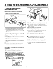
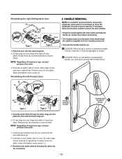
... is the same. Lift up the cover. 3. CAUTION: When lifting the hinge free of the cover (2). Use a flat blade screwdriver to prevent water from the lower hinge pin. 5. Figure 1 - 11 - Open the door. Open the door. Lift up the cover. 3.Rotate the hinge .... (2) (1) (4) (5) (6) (7) Type 1 (3) (5) (7) (6) Rivet Type 2 1. Disconnecting the tube under the door causes about 0.13 gallons (0.5 liters) water to pull the water lines through the lower hinge pin. 7. REMOVING AND REPLACING REFRIGERATOR DOORS Before removing the doors, remove the base grille. Remove the top hinge cover...
... is the same. Lift up the cover. 3. CAUTION: When lifting the hinge free of the cover (2). Use a flat blade screwdriver to prevent water from the lower hinge pin. 5. Figure 1 - 11 - Open the door. Open the door. Lift up the cover. 3.Rotate the hinge .... (2) (1) (4) (5) (6) (7) Type 1 (3) (5) (7) (6) Rivet Type 2 1. Disconnecting the tube under the door causes about 0.13 gallons (0.5 liters) water to pull the water lines through the lower hinge pin. 7. REMOVING AND REPLACING REFRIGERATOR DOORS Before removing the doors, remove the base grille. Remove the top hinge cover...
Owner's Manual
Page 13
...(1) (this may require some force). • The keyhole slots (2) on switch side of corner under edge of hinge lever type. Feed the water tubes through a narrow opening in cabinet top. Install the grounding screw (4) and connect all the wire harnesses (3). 4. Position cover into the connectors.... cover screw (1). Hook tab on door switch side of cover (2) under edge of handle Insert and tighten cover screw (1). 5. Reconnect the water tubes by inserting the tubes into place. Place the door onto the lower hinge pin. 2. CAUTION: When trying to move the refrigerator through...
...(1) (this may require some force). • The keyhole slots (2) on switch side of corner under edge of hinge lever type. Feed the water tubes through a narrow opening in cabinet top. Install the grounding screw (4) and connect all the wire harnesses (3). 4. Position cover into the connectors.... cover screw (1). Hook tab on door switch side of cover (2) under edge of handle Insert and tighten cover screw (1). 5. Reconnect the water tubes by inserting the tubes into place. Place the door onto the lower hinge pin. 2. CAUTION: When trying to move the refrigerator through...

Owner's Manual
Page 16
Water Valve 2. Turn off the water supply. Then separate the Water connection connected to the water valve. 6. Separate the cover back M/C y valve screw. Cover Back M/C Valve Screw 3. Separate the housing and pull out the valve. WATER VALVE DISASSEMBLY METHOD 1. Housing - 15 -
Water Valve 2. Turn off the water supply. Then separate the Water connection connected to the water valve. 6. Separate the cover back M/C y valve screw. Cover Back M/C Valve Screw 3. Separate the housing and pull out the valve. WATER VALVE DISASSEMBLY METHOD 1. Housing - 15 -
Owner's Manual
Page 17
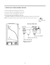
...) 1 to the water valve. 2) Connect the Water Filter tube (OUT) 2 to the water valve. 3) Connect the Ice maker tube (IN) 3 to the water valve. 4) Connect the Water Tank tube (IN) 4 to the water valve until you can see only a line. Water valve Tubes Side View of Water Valve 1 2 3 1 Water Filter (IN) 5/16" 4 2 Water Filter (OUT 1/4" 3 Ice maker (IN) 1/4" 4 Water Tank (IN...
...) 1 to the water valve. 2) Connect the Water Filter tube (OUT) 2 to the water valve. 3) Connect the Ice maker tube (IN) 3 to the water valve. 4) Connect the Water Tank tube (IN) 4 to the water valve until you can see only a line. Water valve Tubes Side View of Water Valve 1 2 3 1 Water Filter (IN) 5/16" 4 2 Water Filter (OUT 1/4" 3 Ice maker (IN) 1/4" 4 Water Tank (IN...
Owner's Manual
Page 18
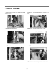
Remove the motor from bracket motor. 6. Pull down drain pipe to 1) - 17 - Using a small phillips screwdriver remove screws from housing and cut tie wrap. 3. 8. Remove fan motor by pushing fan motor in direction of the arrow. 2. Unplug fan motor. 7.- Remove screws from water valve and drain pipe using a phillips screwdriver. 4. FAN MOTOR DISASSEMBLY 1. To reinstall repeat the same process but inverted (6 to remove it. 5.
Remove the motor from bracket motor. 6. Pull down drain pipe to 1) - 17 - Using a small phillips screwdriver remove screws from housing and cut tie wrap. 3. 8. Remove fan motor by pushing fan motor in direction of the arrow. 2. Unplug fan motor. 7.- Remove screws from water valve and drain pipe using a phillips screwdriver. 4. FAN MOTOR DISASSEMBLY 1. To reinstall repeat the same process but inverted (6 to remove it. 5.
Owner's Manual
Page 22
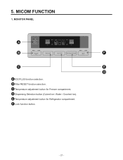
MICOM FUNCTION 1. C Temperature adjustment button for Refrigerator compartment. F Lock function button. - 21 - D Dispensing Selection button (Cubed Ice / Water / Crushed Ice). E Temperature adjustment button for Freezer compartment. 5. B Filter RESET function selection. MONITOR PANEL A B F C E D A ICE PLUS function selection.
MICOM FUNCTION 1. C Temperature adjustment button for Refrigerator compartment. F Lock function button. - 21 - D Dispensing Selection button (Cubed Ice / Water / Crushed Ice). E Temperature adjustment button for Freezer compartment. 5. B Filter RESET function selection. MONITOR PANEL A B F C E D A ICE PLUS function selection.
Owner's Manual
Page 24
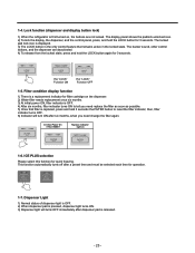
... soon as possible. 5) Once that remains active in the locked state. Filter condition display function 1) There is a replacement indicator for filter cartridge on the dispenser. 2) Water filter needs replacement once six months. 3) At initial power ON, filter indicator is released. - 23 - ICE PLUS selection Please select this function for 3 seconds. In...
... soon as possible. 5) Once that remains active in the locked state. Filter condition display function 1) There is a replacement indicator for filter cartridge on the dispenser. 2) Water filter needs replacement once six months. 3) At initial power ON, filter indicator is released. - 23 - ICE PLUS selection Please select this function for 3 seconds. In...
Owner's Manual
Page 30
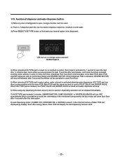
...by 1 second to open the duct door, it remains open , Ice type function can be used to dispense cubed ice, crushed ice and water. 3) Press SELECT ICE TYPE button to illuminate your desired option to be activated to control Duct Motor and GEARED MOTOR. Dispenser Pad has direct... with the main PCB, Main PCB read this can 't be stopped immediately. 7) If ICE TYPE pad exceeds 3 minutes, GEARED MOTOR, CUBE SOLENOID or WATER SOLENOID will turn OFF automatically (this is a protection to avoid the overheating in the mentioned components), the duct motor will be used . - 29 - ...
...by 1 second to open the duct door, it remains open , Ice type function can be used to dispense cubed ice, crushed ice and water. 3) Press SELECT ICE TYPE button to illuminate your desired option to be activated to control Duct Motor and GEARED MOTOR. Dispenser Pad has direct... with the main PCB, Main PCB read this can 't be stopped immediately. 7) If ICE TYPE pad exceeds 3 minutes, GEARED MOTOR, CUBE SOLENOID or WATER SOLENOID will turn OFF automatically (this is a protection to avoid the overheating in the mentioned components), the duct motor will be used . - 29 - ...
Owner's Manual
Page 33
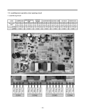
... Circuit LOAD MEASURING PART ON STATUS OFF COMPRESSOR + - 1-4. CON 2 CON 2 PIN 9 PIN 3 115 ~ 127 VAC + CON 3 PIN 5 CON 4 PIN 5 115 ~ 127 VAC 0 VAC 0 VAC 0 VAC WATER VALVE + CON 3 PIN 3 CON 4 PIN 5 115 ~ 127 VAC 0 VAC PIN1 PIN3 PIN5 PIN1 PIN3 PIN5 PIN7 PIN9 PIN11 PIN1 PIN3 PIN5 PIN7 PIN9 PIN1 PIN3...
... Circuit LOAD MEASURING PART ON STATUS OFF COMPRESSOR + - 1-4. CON 2 CON 2 PIN 9 PIN 3 115 ~ 127 VAC + CON 3 PIN 5 CON 4 PIN 5 115 ~ 127 VAC 0 VAC 0 VAC 0 VAC WATER VALVE + CON 3 PIN 3 CON 4 PIN 5 115 ~ 127 VAC 0 VAC PIN1 PIN3 PIN5 PIN1 PIN3 PIN5 PIN7 PIN9 PIN11 PIN1 PIN3 PIN5 PIN7 PIN9 PIN1 PIN3...
Owner's Manual
Page 44
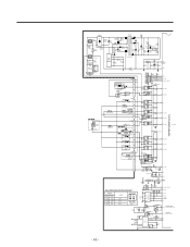
...D8 IN4004 11 3 36 P40 4 5 35 P77_AIN15 6 34 P76_AIN14 RY6(OMIH-SS-112LM) D9 IN4004 10 7 8 33 P75_AIN13 IC7* 9 KID65003AF P60_AIN00 5 ICE WATER 3 PILOT SOLENOID VALVE 1 CON4 5 3 H/BAR-HEATER OPTION 2 RY8 G5NB-1A-E 15 RY9G5NB-1A-E 14 RY10G5NB-1A-E 13 2 32 P74_AIN12 3 31 P73_AIN11 4 ... PS2561-14 10K 29 P71_AIN9 1 56K/2W 2 D10 D11 3 1R0101*2C2C37* IN4007 IN4148 2 XIN CSTS4.00MG03 OSC1 R14* 1M XOUT 3 Table 1. WATER SUPPLYING TIME CONTROL(S/W 2) SWITCH LOCATION(FIG.1) S/W1 S/W2 OFF OFF ON OFF OFF ON ON ON WORK 6.5 s 5.5 s 7.5 s 8.5 s SWITCH ON ON ...
...D8 IN4004 11 3 36 P40 4 5 35 P77_AIN15 6 34 P76_AIN14 RY6(OMIH-SS-112LM) D9 IN4004 10 7 8 33 P75_AIN13 IC7* 9 KID65003AF P60_AIN00 5 ICE WATER 3 PILOT SOLENOID VALVE 1 CON4 5 3 H/BAR-HEATER OPTION 2 RY8 G5NB-1A-E 15 RY9G5NB-1A-E 14 RY10G5NB-1A-E 13 2 32 P74_AIN12 3 31 P73_AIN11 4 ... PS2561-14 10K 29 P71_AIN9 1 56K/2W 2 D10 D11 3 1R0101*2C2C37* IN4007 IN4148 2 XIN CSTS4.00MG03 OSC1 R14* 1M XOUT 3 Table 1. WATER SUPPLYING TIME CONTROL(S/W 2) SWITCH LOCATION(FIG.1) S/W1 S/W2 OFF OFF ON OFF OFF ON ON ON WORK 6.5 s 5.5 s 7.5 s 8.5 s SWITCH ON ON ...
Owner's Manual
Page 45
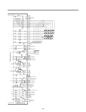
... LD115 LD117 LD119 LD121 LD123 LD114 LD116 LD118 LD120 LD122 LD124 (ÉÙ 7) LD125 LD126 R10160 (É¥ 7) (CUBE 8l) (WATER 8l) (CRUSH 8l) LD127 LD129 LD130 LD131 LD128 LD132(WATER FIG.) (CUBE FIG.) LD133 LD135 LD134 R102 R103 LD136 (CRUSH R104 LD137 FIG.) 120 120 120 (ÉÙ OFF) (É¥...
... LD115 LD117 LD119 LD121 LD123 LD114 LD116 LD118 LD120 LD122 LD124 (ÉÙ 7) LD125 LD126 R10160 (É¥ 7) (CUBE 8l) (WATER 8l) (CRUSH 8l) LD127 LD129 LD130 LD131 LD128 LD132(WATER FIG.) (CUBE FIG.) LD133 LD135 LD134 R102 R103 LD136 (CRUSH R104 LD137 FIG.) 120 120 120 (ÉÙ OFF) (É¥...
Owner's Manual
Page 46
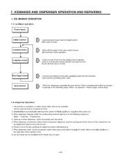
Ice Maker operation 1-2. The function is available in models where water and ice are available without opening freezer compartment door. ª ª - 45 - ICE MAKER OPERATION 1-1. Dispenser Operation 1. ICEMAKER AND DISPENSER OPERATION AND REPAIRING 1. 7.
Ice Maker operation 1-2. The function is available in models where water and ice are available without opening freezer compartment door. ª ª - 45 - ICE MAKER OPERATION 1-1. Dispenser Operation 1. ICEMAKER AND DISPENSER OPERATION AND REPAIRING 1. 7.
Owner's Manual
Page 47
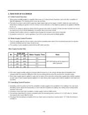
Water Supply Control Function No DISP S/W S1 S2 Water Supply Time Note 1 OFF OFF 9.0 2 ON OFF 3 OFF ON 8.0 DIP S/W Setting will be depend of 10.0 water pressure 4 ON ON 11.0 2-3. Icemaking Control Function - 46 - 2. FUNCTION OF ICE MAKER 2-1. Initial Control Function Pin No. 44. 2-2.
Water Supply Control Function No DISP S/W S1 S2 Water Supply Time Note 1 OFF OFF 9.0 2 ON OFF 3 OFF ON 8.0 DIP S/W Setting will be depend of 10.0 water pressure 4 ON ON 11.0 2-3. Icemaking Control Function - 46 - 2. FUNCTION OF ICE MAKER 2-1. Initial Control Function Pin No. 44. 2-2.


