Owner's Manual
Page 3
... Panel...21 6. Explanation for PCB circuit 30 7. CIRCUIT DIAGRAM...51 9. Install Water Filter...7 3. MICOM FUNCTION ...21 1. Ice maker Troubleshooting 49 4. DISASSEMBLY ...6 1. How to Control the amount of water supplied to Remove Swtich Lamp 13 4. Water Valve Tubes Assembly Method 16 8. Icemaker Circuit...50 8. Water Valve Disassembly Method 15 7. EXPLANATION FOR MICOM CIRCUIT 30 1. ICEMAKER AND DISPENSER...
... Panel...21 6. Explanation for PCB circuit 30 7. CIRCUIT DIAGRAM...51 9. Install Water Filter...7 3. MICOM FUNCTION ...21 1. Ice maker Troubleshooting 49 4. DISASSEMBLY ...6 1. How to Control the amount of water supplied to Remove Swtich Lamp 13 4. Water Valve Tubes Assembly Method 16 8. Icemaker Circuit...50 8. Water Valve Disassembly Method 15 7. EXPLANATION FOR MICOM CIRCUIT 30 1. ICEMAKER AND DISPENSER...
Owner's Manual
Page 5
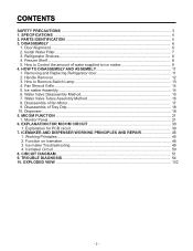
1. SPECIFICATIONS GENERAL FEATURES MODELS LSC27914SB /01 LSC27914SW /01 LSC27914TT /01 LSC27914ST /01 FREEZER ... Device Anti-freezing Heater Case Material Door Material Handle Type Display Graphic Basket Lamp Shelf Tray meat Egg Bank Ice Maker Basket Lamp Shelf Black PCM Super White Titanium Stainless 36 x 33 x 70 in 328.5 lbs 27 cuft...POE) 310 ± 10 cc MOLECULAR SIEVE XH-7 ID Ø0.80 4 Hours 13 - 70 Hours Heater, Sheath Water Tank Heater Embo (normal) PCM VCM Vista (plastic) ICE PLUS 3full+1half Yes (2) 40W/Blue 1 (Fix) + 2 (S/Out) Yes No Twisting 4 plastic Yes (1) ...
1. SPECIFICATIONS GENERAL FEATURES MODELS LSC27914SB /01 LSC27914SW /01 LSC27914TT /01 LSC27914ST /01 FREEZER ... Device Anti-freezing Heater Case Material Door Material Handle Type Display Graphic Basket Lamp Shelf Tray meat Egg Bank Ice Maker Basket Lamp Shelf Black PCM Super White Titanium Stainless 36 x 33 x 70 in 328.5 lbs 27 cuft...POE) 310 ± 10 cc MOLECULAR SIEVE XH-7 ID Ø0.80 4 Hours 13 - 70 Hours Heater, Sheath Water Tank Heater Embo (normal) PCM VCM Vista (plastic) ICE PLUS 3full+1half Yes (2) 40W/Blue 1 (Fix) + 2 (S/Out) Yes No Twisting 4 plastic Yes (1) ...
Owner's Manual
Page 10
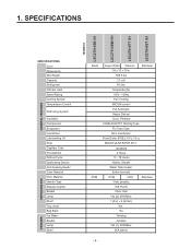
... . DISASSEMBLY ICEMAKER COVER If you need acces to the drawing below . 1. WATER SUPPLIED TO ICE MAKER 1) Press the test switch under the ice tray and press test switch. 4) When the ice tray rotates, the water in the right figure spilled water and discard it out ‚ . Power Switch ON/OFF 2. If the... ice bin does not slide into the tray two or three times....
... . DISASSEMBLY ICEMAKER COVER If you need acces to the drawing below . 1. WATER SUPPLIED TO ICE MAKER 1) Press the test switch under the ice tray and press test switch. 4) When the ice tray rotates, the water in the right figure spilled water and discard it out ‚ . Power Switch ON/OFF 2. If the... ice bin does not slide into the tray two or three times....
Owner's Manual
Page 17
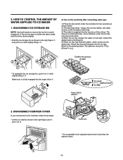
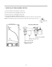
... a Red mark on the end that connects to the water valve until you can see only a line. 7. WATER VALVE TUBES ASSEMBLY METHOD 1) Connect the Water Filter tube (IN) 1 to the water valve. 2) Connect the Water Filter tube (OUT) 2 to the water valve. 3) Connect the Ice maker tube (IN) 3 to the water valve. 4) Connect the Water Tank tube (IN) 4 to the...
... a Red mark on the end that connects to the water valve until you can see only a line. 7. WATER VALVE TUBES ASSEMBLY METHOD 1) Connect the Water Filter tube (IN) 1 to the water valve. 2) Connect the Water Filter tube (OUT) 2 to the water valve. 3) Connect the Ice maker tube (IN) 3 to the water valve. 4) Connect the Water Tank tube (IN) 4 to the...
Owner's Manual
Page 45
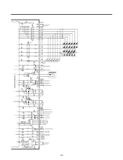
...LD118 LD120 LD122 LD124 (ÉÙ 7) LD125 LD126 R10160 (É¥ 7) (CUBE 8l) (WATER 8l) (CRUSH 8l) LD127 LD129 LD130 LD131 LD128 LD132(WATER FIG.) (CUBE FIG.) LD133 LD135 LD134 R102 R103 LD136 (CRUSH R104 LD137 FIG.) 120 120 ...2K 1 DAMPER,HEATER 2 3 C H/BAR-DOOR S/W 4 D R-DOOR S/W 5 R1-SENSOR 6 7 R2-SENSOR 8 A 9 A 10 B 11 12 B STEPPING MOTOR 13 CON8 1 ICE MAKER SENSOR 2 3 ICE MAKER 4 STOP S/W 5 6 2 ICE MAKER TEST S/W 7 3 HALL 1 IC 78 + CE15 8 R65* 4.7K R66* 4.7K Forward 5 Reverse 6 100uF /25V 10 9 R67 IC11 4 BA6222 68,1/2W CM4 CC27* 3 ...
...LD118 LD120 LD122 LD124 (ÉÙ 7) LD125 LD126 R10160 (É¥ 7) (CUBE 8l) (WATER 8l) (CRUSH 8l) LD127 LD129 LD130 LD131 LD128 LD132(WATER FIG.) (CUBE FIG.) LD133 LD135 LD134 R102 R103 LD136 (CRUSH R104 LD137 FIG.) 120 120 ...2K 1 DAMPER,HEATER 2 3 C H/BAR-DOOR S/W 4 D R-DOOR S/W 5 R1-SENSOR 6 7 R2-SENSOR 8 A 9 A 10 B 11 12 B STEPPING MOTOR 13 CON8 1 ICE MAKER SENSOR 2 3 ICE MAKER 4 STOP S/W 5 6 2 ICE MAKER TEST S/W 7 3 HALL 1 IC 78 + CE15 8 R65* 4.7K R66* 4.7K Forward 5 Reverse 6 100uF /25V 10 9 R67 IC11 4 BA6222 68,1/2W CM4 CC27* 3 ...
Owner's Manual
Page 46
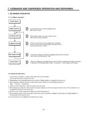
ICE MAKER OPERATION 1-1. The function is available in models where water and ice are available without opening freezer compartment door. ª ª - 45 - ICEMAKER AND DISPENSER OPERATION AND REPAIRING 1. Ice Maker operation 1-2. Dispenser Operation 1. 7.
ICE MAKER OPERATION 1-1. The function is available in models where water and ice are available without opening freezer compartment door. ª ª - 45 - ICEMAKER AND DISPENSER OPERATION AND REPAIRING 1. Ice Maker operation 1-2. Dispenser Operation 1. 7.
Owner's Manual
Page 47
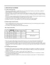
Initial Control Function Pin No. 44. 2-2. Icemaking Control Function - 46 - FUNCTION OF ICE MAKER 2-1. Water Supply Control Function No DISP S/W S1 S2 Water Supply Time Note 1 OFF OFF 9.0 2 ON OFF 3 OFF ON 8.0 DIP S/W Setting will be depend of 10.0 water pressure 4 ON ON 11.0 2-3. 2.
Initial Control Function Pin No. 44. 2-2. Icemaking Control Function - 46 - FUNCTION OF ICE MAKER 2-1. Water Supply Control Function No DISP S/W S1 S2 Water Supply Time Note 1 OFF OFF 9.0 2 ON OFF 3 OFF ON 8.0 DIP S/W Setting will be depend of 10.0 water pressure 4 ON ON 11.0 2-3. 2.
Owner's Manual
Page 51
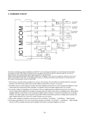
...water supply time is supplied to the icemaker cube mold through the solenoid relay for ice valve of solenoid valve in the freezer and icemaker driving part of main PWB. ª ª ª ª ª ª - 50 - This circuit is the same as ice ejection of icemaker cube mold, ice...16.2KF R59 2K CE14 10uF /50V R61 4.7K R64* 2K CON8 1 2 ICE MAKER SENSOR 3 ICE MAKER 4 STOP S/W 5 ICE MAKER 6 TEST S/W 2 7 3 HALL 1 IC + CE15 8 100uF /25V 10 9 R67 68,1/2W CM4 2 1 223/100V 10 M ICE MAKER MOTOR P67_AIN07_STOP3 27 P70_AIN8 28 R25* R24* 4.7K 4.7K SW 2 2 1 The...
...water supply time is supplied to the icemaker cube mold through the solenoid relay for ice valve of solenoid valve in the freezer and icemaker driving part of main PWB. ª ª ª ª ª ª - 50 - This circuit is the same as ice ejection of icemaker cube mold, ice...16.2KF R59 2K CE14 10uF /50V R61 4.7K R64* 2K CON8 1 2 ICE MAKER SENSOR 3 ICE MAKER 4 STOP S/W 5 ICE MAKER 6 TEST S/W 2 7 3 HALL 1 IC + CE15 8 100uF /25V 10 9 R67 68,1/2W CM4 2 1 223/100V 10 M ICE MAKER MOTOR P67_AIN07_STOP3 27 P70_AIN8 28 R25* R24* 4.7K 4.7K SW 2 2 1 The...
Owner's Manual
Page 52
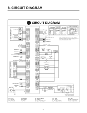
... FUSE-M SHEATH-HTR 115V/60Hz DISPENSER LEVEL S/W FUSE-M F-DOOR S/W c d F-LAMP M AUGER MOTOR ICE VALVE WATER VALVE PILOT VALVE R-LAMPS a b R-DOOR S/W OLP CAPACITOR PART CR COMP' CS M 3 6 1 CS 5 2 P.T.C COMP' ACCESSORIES - 51 - CIRCUIT DIAGRAM CIRCUIT DIAGRAM ICE MAKER UNIT M I/M MOTOR HALL IC I/M TEST S/W S/W ICE MAKER PART STOP S/W I/M SENSOR STEPPING MOTOR R2-SENSOR R1-SENSOR R-DOOR a PERCEPTION S/W b DAMPER-HTR...
... FUSE-M SHEATH-HTR 115V/60Hz DISPENSER LEVEL S/W FUSE-M F-DOOR S/W c d F-LAMP M AUGER MOTOR ICE VALVE WATER VALVE PILOT VALVE R-LAMPS a b R-DOOR S/W OLP CAPACITOR PART CR COMP' CS M 3 6 1 CS 5 2 P.T.C COMP' ACCESSORIES - 51 - CIRCUIT DIAGRAM CIRCUIT DIAGRAM ICE MAKER UNIT M I/M MOTOR HALL IC I/M TEST S/W S/W ICE MAKER PART STOP S/W I/M SENSOR STEPPING MOTOR R2-SENSOR R1-SENSOR R-DOOR a PERCEPTION S/W b DAMPER-HTR...
Owner's Manual
Page 117
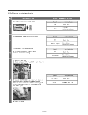
.... NOTE: Refer to Step 5 Replace Main PCB 4) Check the result. - 116 - CHECKING FLOW Check for Ice maker power S/W status. 1 Check the water supply connection to catch the water supplied in order to outlet. 2 Check cube / Crush mode function. RESULT & SERVICE ACTION Result ON OFF Service Action Go ... explain to customer CON 4 CON 3 4 3) Execute TEST MODE in Ice maker as is shown in the picture (PILOT VALVE). 22) Refrigerator is shown in the picture (NOTE: Be sure to locate a recipient below ice maker in test mode) water supply will be activated at the end of Test cycle.
.... NOTE: Refer to Step 5 Replace Main PCB 4) Check the result. - 116 - CHECKING FLOW Check for Ice maker power S/W status. 1 Check the water supply connection to catch the water supplied in order to outlet. 2 Check cube / Crush mode function. RESULT & SERVICE ACTION Result ON OFF Service Action Go ... explain to customer CON 4 CON 3 4 3) Execute TEST MODE in Ice maker as is shown in the picture (PILOT VALVE). 22) Refrigerator is shown in the picture (NOTE: Be sure to locate a recipient below ice maker in test mode) water supply will be activated at the end of Test cycle.
Owner's Manual
Page 118
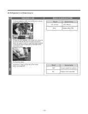
22) Refrigerator is shown in the picture (NOTE: Be sure to locate a recipient below ice maker in order to catch the water supplied in the picture (ICE VALVE). In previous 2 steps, at the end of Test mode, water was supplied? 6 Result YES NO Service Action Normal, explain to Step 5 Other Replace Main ...PCB CON 4 CON 3 5 3) Execute TEST MODE in Ice maker as is shown in test mode) water supply will be activated at the end of Test cycle. CHECKING FLOW 1) Check voltage in CON 3 and CON 4 as is not dispensing ice NO. TEST S/W 4) Check the result. RESULT & SERVICE ...
22) Refrigerator is shown in the picture (NOTE: Be sure to locate a recipient below ice maker in order to catch the water supplied in the picture (ICE VALVE). In previous 2 steps, at the end of Test mode, water was supplied? 6 Result YES NO Service Action Normal, explain to Step 5 Other Replace Main ...PCB CON 4 CON 3 5 3) Execute TEST MODE in Ice maker as is shown in test mode) water supply will be activated at the end of Test cycle. CHECKING FLOW 1) Check voltage in CON 3 and CON 4 as is not dispensing ice NO. TEST S/W 4) Check the result. RESULT & SERVICE ...

Specification
Page 2
...Water Dispenser Automatic Ice Maker IcePlus™ Freezer Light 16.2 cu.ft. 10.2 cu.ft. 26.5 cu.ft. All other product and brand names are approximate. "LG Life's Good" is a registered trademark of Shelves Shelf Configuration Shelf Construction Crisper Bins Refrigerator Light REFRIGERATOR DOOR No. Energy Star LED (Temperature R/F, Ice Options, Child Lock, Water... System UPC CODES LSC27914SW Smooth White 048231 783361 LSC27914SB Smooth Black 048231 783378 LSC27914ST Stainless Steel 048231 783347 www.LG.com LG Electronics U.S.A., Inc. 1000 Sylvan Avenue Englewood Cliffs...
...Water Dispenser Automatic Ice Maker IcePlus™ Freezer Light 16.2 cu.ft. 10.2 cu.ft. 26.5 cu.ft. All other product and brand names are approximate. "LG Life's Good" is a registered trademark of Shelves Shelf Configuration Shelf Construction Crisper Bins Refrigerator Light REFRIGERATOR DOOR No. Energy Star LED (Temperature R/F, Ice Options, Child Lock, Water... System UPC CODES LSC27914SW Smooth White 048231 783361 LSC27914SB Smooth Black 048231 783378 LSC27914ST Stainless Steel 048231 783347 www.LG.com LG Electronics U.S.A., Inc. 1000 Sylvan Avenue Englewood Cliffs...


