

Service Manual
Page 2
......12 FILTER ...13 HOW TO CONTROL THE ICEMAKER WATER SUPPLY 14 MICOM FUNCTION ...16 EXPLANATION OF MICOM CIRCUIT ...30 EXPLANATION OF PWB CIRCUIT ...30 PWB PARTS DIAGRAM AND LIST...46 PWB CIRCUIT DIAGRAM ...52 OPERATION PRINCIPLE AND REPAIR METHOD OF ICEMAKER 54 OPERATION PRINCIPLE...54 CONTROL METHOD ACCORDING TO FUNCTIONS...55... CLAIMS ...95 HOW TO DISASSEMBLE AND ASSEMBLE ...100 DOOR...100 HANDLE ...101 FAN SHROUD GRILLE ...102 ICEMAKER ASSEMBLY...102 DISPENSER...103 EXPLODED VIEW ...105 REPLACEMENT PARTS LIST...119 -2-
......12 FILTER ...13 HOW TO CONTROL THE ICEMAKER WATER SUPPLY 14 MICOM FUNCTION ...16 EXPLANATION OF MICOM CIRCUIT ...30 EXPLANATION OF PWB CIRCUIT ...30 PWB PARTS DIAGRAM AND LIST...46 PWB CIRCUIT DIAGRAM ...52 OPERATION PRINCIPLE AND REPAIR METHOD OF ICEMAKER 54 OPERATION PRINCIPLE...54 CONTROL METHOD ACCORDING TO FUNCTIONS...55... CLAIMS ...95 HOW TO DISASSEMBLE AND ASSEMBLE ...100 DOOR...100 HANDLE ...101 FAN SHROUD GRILLE ...102 ICEMAKER ASSEMBLY...102 DISPENSER...103 EXPLODED VIEW ...105 REPLACEMENT PARTS LIST...119 -2-

Service Manual
Page 3
...is properly grounded. Particularly in the refrigerator. 13. Make sure hooks are not likely to prevent accident or injury when servicing. 1. Replace the parts or mask with full of the refrigerator, especially something containing water, like a vase. 14. Disconnect power cord from wall outlet and wait for... more than three minutes before replacing PWB parts. If the power plug was damaged, it may cause a fire. If the wall outlet is overloaded, it could cause fire, injury, or...
...is properly grounded. Particularly in the refrigerator. 13. Make sure hooks are not likely to prevent accident or injury when servicing. 1. Replace the parts or mask with full of the refrigerator, especially something containing water, like a vase. 14. Disconnect power cord from wall outlet and wait for... more than three minutes before replacing PWB parts. If the power plug was damaged, it may cause a fire. If the wall outlet is overloaded, it could cause fire, injury, or...

Service Manual
Page 8
Water Filter Dairy Product Corner Lamp Shelf Can Server Grab and Go Egg Box Snack Drawer Bottle Guide Shelf Door Rack Vegetable Drawer OptiChill PARTS IDENTIFICATION 1. Ref No. : GR-L267AV(T)BA PWB Cover Frame Display Dispenser Lamp Ice & Water Dispenser Button Water Tubes Door Rack Automatic Icemaker Lamp Shelf Door Rack Drawer (Wire/Plastic) Door Rack Lower Cover Freezer Compartment Refrigerator Compartment OptiChill Display Humidity Switch -8-
Water Filter Dairy Product Corner Lamp Shelf Can Server Grab and Go Egg Box Snack Drawer Bottle Guide Shelf Door Rack Vegetable Drawer OptiChill PARTS IDENTIFICATION 1. Ref No. : GR-L267AV(T)BA PWB Cover Frame Display Dispenser Lamp Ice & Water Dispenser Button Water Tubes Door Rack Automatic Icemaker Lamp Shelf Door Rack Drawer (Wire/Plastic) Door Rack Lower Cover Freezer Compartment Refrigerator Compartment OptiChill Display Humidity Switch -8-

Service Manual
Page 9
Water Filter Dairy Product Corner Lamp Shelf Grab and Go Wine Holder Egg Box Snack Drawer Bottle Guide Shelf Door Rack Vegetable Drawer OptiChill PARTS IDENTIFICATION 2. Ref No. : GR-L267AV(T)FA PWB Cover Frame Display Dispenser Lamp Ice & Water Dispenser Button Water Tubes Door Rack Automatic Icemaker Lamp Shelf Door Rack Drawer (Wire/Plastic) Door Rack Lower Cover Freezer Compartment Refrigerator Compartment OptiChill Display Humidity Switch -9-
Water Filter Dairy Product Corner Lamp Shelf Grab and Go Wine Holder Egg Box Snack Drawer Bottle Guide Shelf Door Rack Vegetable Drawer OptiChill PARTS IDENTIFICATION 2. Ref No. : GR-L267AV(T)FA PWB Cover Frame Display Dispenser Lamp Ice & Water Dispenser Button Water Tubes Door Rack Automatic Icemaker Lamp Shelf Door Rack Drawer (Wire/Plastic) Door Rack Lower Cover Freezer Compartment Refrigerator Compartment OptiChill Display Humidity Switch -9-

Service Manual
Page 10
PARTS IDENTIFICATION 3. Ref No. : GR-L267AV(T)RA, PWB Cover Frame Display Dispenser Lamp Ice & Water Dispenser Button Water Tubes Door Rack Automatic Icemaker Lamp Shelf Door Rack Drawer (Wire/Plastic) Door Rack Lower Cover Freezer Compartment Refrigerator Compartment Humidity Switch - 10 - Water Filter Dairy Product Corner Lamp Shelf Door Rack Wine Holder Egg Box Snack Drawer Bottle Guide Shelf Door Rack Vegetable Drawer Vegetable Drawer /Meat Drawer
PARTS IDENTIFICATION 3. Ref No. : GR-L267AV(T)RA, PWB Cover Frame Display Dispenser Lamp Ice & Water Dispenser Button Water Tubes Door Rack Automatic Icemaker Lamp Shelf Door Rack Drawer (Wire/Plastic) Door Rack Lower Cover Freezer Compartment Refrigerator Compartment Humidity Switch - 10 - Water Filter Dairy Product Corner Lamp Shelf Door Rack Wine Holder Egg Box Snack Drawer Bottle Guide Shelf Door Rack Vegetable Drawer Vegetable Drawer /Meat Drawer

Service Manual
Page 11
PARTS IDENTIFICATION 4. Water Filter Dairy Product Corner Lamp Shelf Door Rack Wine Holder Egg Box Snack Drawer Bottle Guide Shelf Door Rack Vegetable Drawer Vegetable Drawer /Meat Drawer Ref No. : GR-L267DV(T)R PWB Cover Frame Display Dispenser Lamp Ice & Water Dispenser Button Water Tubes Door Rack Automatic Icemaker Lamp Shelf Door Rack Drawer (Wire/Plastic) Door Rack Lower Cover Freezer Compartment Refrigerator Compartment Humidity Switch - 11 -
PARTS IDENTIFICATION 4. Water Filter Dairy Product Corner Lamp Shelf Door Rack Wine Holder Egg Box Snack Drawer Bottle Guide Shelf Door Rack Vegetable Drawer Vegetable Drawer /Meat Drawer Ref No. : GR-L267DV(T)R PWB Cover Frame Display Dispenser Lamp Ice & Water Dispenser Button Water Tubes Door Rack Automatic Icemaker Lamp Shelf Door Rack Drawer (Wire/Plastic) Door Rack Lower Cover Freezer Compartment Refrigerator Compartment Humidity Switch - 11 -

Service Manual
Page 13
... water dispenser decreases noticeably. 2. NOTE: There will hear the snap when it stops. To purchase replacement water filter cartridges, visit your local appliance dealer or part distributor. - Pull out the cartridge. Catch it click . NOTE: - Push it in the line, causing noise or hissing. Flush the Water System After Replacing Filter...
... water dispenser decreases noticeably. 2. NOTE: There will hear the snap when it stops. To purchase replacement water filter cartridges, visit your local appliance dealer or part distributor. - Pull out the cartridge. Catch it click . NOTE: - Push it in the line, causing noise or hissing. Flush the Water System After Replacing Filter...

Service Manual
Page 14
... hurt your hands. 2 1 Water supply amount TABLE STAGE TIME TO SUPPLY 1 4 sec. 2 4.5 sec. 3 5 sec. 4 5.5 sec. 5 6 sec. Pull out the ice bin shelf in the upper part of Water Supplied to the icemaker. 1. Confirm the amount of water supplied to Icemaker. 3-1. HOW TO INSTALL REFRIGERATOR 3.
... hurt your hands. 2 1 Water supply amount TABLE STAGE TIME TO SUPPLY 1 4 sec. 2 4.5 sec. 3 5 sec. 4 5.5 sec. 5 6 sec. Pull out the ice bin shelf in the upper part of Water Supplied to the icemaker. 1. Confirm the amount of water supplied to Icemaker. 3-1. HOW TO INSTALL REFRIGERATOR 3.
Service Manual
Page 15
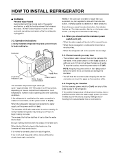
... to O (off ). If the refrigerator is the next after the 5th step.) 3-3. HOW TO INSTALL REFRIGERATOR w WARNING Personal Injury Hazard Avoid contact with the moving parts of the ejector mechanism, or with water. Icemaker Cube Size Indicator Light Feeler Arm Power Switch Water Supply Control Switch The icemaker will become cloudy...
... to O (off ). If the refrigerator is the next after the 5th step.) 3-3. HOW TO INSTALL REFRIGERATOR w WARNING Personal Injury Hazard Avoid contact with the moving parts of the ejector mechanism, or with water. Icemaker Cube Size Indicator Light Feeler Arm Power Switch Water Supply Control Switch The icemaker will become cloudy...
Service Manual
Page 17
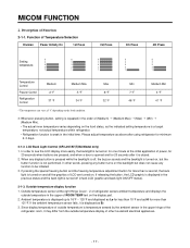
... the special freezing button and the freezing temperature adjustment button for minimum 2~3 days. 2-1-2. If the ambient temperature sensor fails, it is turned on the display part. 2. Outside temperature sensor at the initial application of other words, pressing any display button is pressed while the backlight is off (check LCD graphic and...
... the special freezing button and the freezing temperature adjustment button for minimum 2~3 days. 2-1-2. If the ambient temperature sensor fails, it is turned on the display part. 2. Outside temperature sensor at the initial application of other words, pressing any display button is pressed while the backlight is off (check LCD graphic and...

Service Manual
Page 25
... circuit overload from everything starting at once. Function When temperature of the defrost sensor surpasses 41°F (5°C). Sequential operation of built-in product Electromechanical parts of the appliance, such as the compressor, defrost heater, freezer fan, cooling fan, and damper motor, are operated sequentially as shown in the chart below...
... circuit overload from everything starting at once. Function When temperature of the defrost sensor surpasses 41°F (5°C). Sequential operation of built-in product Electromechanical parts of the appliance, such as the compressor, defrost heater, freezer fan, cooling fan, and damper motor, are operated sequentially as shown in the chart below...
Service Manual
Page 26
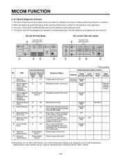
... ROOM TEMP CRUSH FRZ TEMP REF TEMP 3 SECS LOCK DISPENSER & KEY ) * , q : Proper operation Failure code indication part Product operation status in the drawings below. Item Freezernotch Refrigeratornotch Contents of failure temperature temperature display display Compressor Freezing BLDC motor Cooling BLDC...sensor short circuit ONfor15minutes/ Standard q q q freezer sensor OFFfor15minutes RPM 2 Abnormal refrigerator Er sensor 1 (R1) (Upper part in the refrigerator compartment) 4 Abnormal defrost Er sensor dS Abnormal short circuit q Standard q No defrost q RPM 5 ...
... ROOM TEMP CRUSH FRZ TEMP REF TEMP 3 SECS LOCK DISPENSER & KEY ) * , q : Proper operation Failure code indication part Product operation status in the drawings below. Item Freezernotch Refrigeratornotch Contents of failure temperature temperature display display Compressor Freezing BLDC motor Cooling BLDC...sensor short circuit ONfor15minutes/ Standard q q q freezer sensor OFFfor15minutes RPM 2 Abnormal refrigerator Er sensor 1 (R1) (Upper part in the refrigerator compartment) 4 Abnormal defrost Er sensor dS Abnormal short circuit q Standard q No defrost q RPM 5 ...

Service Manual
Page 27
...: LED or LCD graphic on the (C) part turns on Abnormal: LED or LCD graphic on the (C) part turns off Normal: LED or LCD graphic on the (D) part turns on Abnormal: LED or LCD graphic on the (D) part turns off Normal: LEDs or LCDs graphic on the (E) part turns on Abnormal: LEDs or LCDs graphic... and water tank sensor are also used to check the display. Release the buttons and the display will function normally. This will turn on the (E) part turns off The other display elements will return to its usual state. - 27 - The exception is that when the ambient temperature sensor fails, it ...
...: LED or LCD graphic on the (C) part turns on Abnormal: LED or LCD graphic on the (C) part turns off Normal: LED or LCD graphic on the (D) part turns on Abnormal: LED or LCD graphic on the (D) part turns off Normal: LEDs or LCDs graphic on the (E) part turns on Abnormal: LEDs or LCDs graphic... and water tank sensor are also used to check the display. Release the buttons and the display will function normally. This will turn on the (E) part turns off The other display elements will return to its usual state. - 27 - The exception is that when the ambient temperature sensor fails, it ...

Service Manual
Page 30
Caution : Since high voltage (160 Vdc) is as follows: Part Voltage VA1 120 Vac CE1 160 Vdc CE2 14 Vdc CE3 12 Vdc CE4 15.5 Vdc CE5 5 Vdc - 30 - Voltage of a rectifier (BD1 and CE1) ...converting AC to dissipate. Explanation for PWB circuit 1-1. GR-L267**** The power circuit includes a Switched Mode Power Supply (SMPS). It consists of every part is maintained at the power terminal, wait at least 3 minutes after unplugging the appliance to check the voltages to allow the current to DC, a switch...
Caution : Since high voltage (160 Vdc) is as follows: Part Voltage VA1 120 Vac CE1 160 Vdc CE2 14 Vdc CE3 12 Vdc CE4 15.5 Vdc CE5 5 Vdc - 30 - Voltage of a rectifier (BD1 and CE1) ...converting AC to dissipate. Explanation for PWB circuit 1-1. GR-L267**** The power circuit includes a Switched Mode Power Supply (SMPS). It consists of every part is maintained at the power terminal, wait at least 3 minutes after unplugging the appliance to check the voltages to allow the current to DC, a switch...

Service Manual
Page 31
The oscillator (OSC1) must always be replaced with an exact rated part, because if this spec is 5 Vdc. During normal operation, the voltage at all. If the reset fails, the MICOM will be restarted from the initial ... and time calculation related to the transmission of the MICOM, such as RAM, defrosting, etc., to reset itself. Reset circuit The RESET circuit allows various parts of data and calculations made by the MICOM (IC1). Oscillation circuit The oscillation circuit generates a basic clock signal for 10 ms causes the MICOM to...
The oscillator (OSC1) must always be replaced with an exact rated part, because if this spec is 5 Vdc. During normal operation, the voltage at all. If the reset fails, the MICOM will be restarted from the initial ... and time calculation related to the transmission of the MICOM, such as RAM, defrosting, etc., to reset itself. Reset circuit The RESET circuit allows various parts of data and calculations made by the MICOM (IC1). Oscillation circuit The oscillation circuit generates a basic clock signal for 10 ms causes the MICOM to...

Service Manual
Page 32
... at the regular speed even if the door of Load Frost Removal AC Converting Refrigerator Compressor Heater Relay LAMP Dispensor Heater Magic room Heater Measuring part (IC6) Status ON OFF IC6-14 IC6-10 IC7-16 IC6-13 Within 1 V 12 V IC6-11 IC6-12 REF REF - 32 - When the doors are...
... at the regular speed even if the door of Load Frost Removal AC Converting Refrigerator Compressor Heater Relay LAMP Dispensor Heater Magic room Heater Measuring part (IC6) Status ON OFF IC6-14 IC6-10 IC7-16 IC6-13 Within 1 V 12 V IC6-11 IC6-12 REF REF - 32 - When the doors are...

Service Manual
Page 33
EXPLANATION FOR MICOM CIRCUIT 2. Dispenser operation circuit 1) Check load driving status Type of Load GEARED MOTOR Measuring part Status ON OFF IC7-15 2) Lever Switch sensing circuit Measuring part Lever S/W On(Press) OFF SOLENOID CUBE WATER VALVE WATER IC7-14 Within 1 V 12 V IC7-13 IC1(Micom) (No. 16) 5 V (60 Hz) 0 V 5V SOLENOID DISPENSER IC7-12 - 33 -
EXPLANATION FOR MICOM CIRCUIT 2. Dispenser operation circuit 1) Check load driving status Type of Load GEARED MOTOR Measuring part Status ON OFF IC7-15 2) Lever Switch sensing circuit Measuring part Lever S/W On(Press) OFF SOLENOID CUBE WATER VALVE WATER IC7-14 Within 1 V 12 V IC7-13 IC1(Micom) (No. 16) 5 V (60 Hz) 0 V 5V SOLENOID DISPENSER IC7-12 - 33 -

Service Manual
Page 34
Switch at both ends are interconnected, if either fails, the other will not respond properly. ✽ If either switch fails, the light will not come on. - 34 - D . B , C - D . B , C - Switch at both ends are at On status) ✽ Since door switches (A) and (B) are at Off status) 5 V ( A - Door opening sensing circuit 1) GR-L267**** Measuring part Door of Freezer / Refrigerator Closing Opening IC1 (MICOM) No. 47, 46 Pin 5 V ( A - EXPLANATION FOR MICOM CIRCUIT 3.
Switch at both ends are interconnected, if either fails, the other will not respond properly. ✽ If either switch fails, the light will not come on. - 34 - D . B , C - D . B , C - Switch at both ends are at On status) ✽ Since door switches (A) and (B) are at Off status) 5 V ( A - Door opening sensing circuit 1) GR-L267**** Measuring part Door of Freezer / Refrigerator Closing Opening IC1 (MICOM) No. 47, 46 Pin 5 V ( A - EXPLANATION FOR MICOM CIRCUIT 3.

Service Manual
Page 38
.... 3. The circuit cuts all power to the fan when it senses a lock-up condition. 1) GR-L267**** Motor OFF Motor ON a , d part 5V 2 ~ 3V b part 2V or less 12 ~ 14V e part 2V or less 8 ~ 16V c , f part 0 V 0 V COMPRESSOR -FAN PWM COMPRESSOR -FAN LOCK FREEZER-FAN PWM FREEZER-FAN LOCK - 38 - This circuit changes the speed of...
.... 3. The circuit cuts all power to the fan when it senses a lock-up condition. 1) GR-L267**** Motor OFF Motor ON a , d part 5V 2 ~ 3V b part 2V or less 12 ~ 14V e part 2V or less 8 ~ 16V c , f part 0 V 0 V COMPRESSOR -FAN PWM COMPRESSOR -FAN LOCK FREEZER-FAN PWM FREEZER-FAN LOCK - 38 - This circuit changes the speed of...

Service Manual
Page 43
This delay is ±5%. An analog tester has to great a margin of the PWB ASSEMBLY and the MAIN part. - 43 - u Resistance of the freezing sensor shall be measured with a digital tester after separating CON8 of that sensor to measure the ... a digital tester after separating CON7 of error. u When measuring the resistance value of the sensor, allow the temperature of the PWB ASSEMBLY and the MAIN part. EXPLANATION FOR MICOM CIRCUIT 2) Sensor resistance characteristics table Measuring Temperature (°C) -20 °C -15 °C -15 °C -5 °C 0 °C +5 °C +10 ...
This delay is ±5%. An analog tester has to great a margin of the PWB ASSEMBLY and the MAIN part. - 43 - u Resistance of the freezing sensor shall be measured with a digital tester after separating CON8 of that sensor to measure the ... a digital tester after separating CON7 of error. u When measuring the resistance value of the sensor, allow the temperature of the PWB ASSEMBLY and the MAIN part. EXPLANATION FOR MICOM CIRCUIT 2) Sensor resistance characteristics table Measuring Temperature (°C) -20 °C -15 °C -15 °C -5 °C 0 °C +5 °C +10 ...


