
Service Manual
Page 2
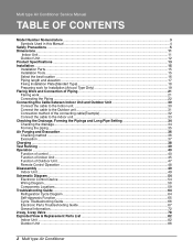
... Unit ...45 Function of Outdoor Unit ...47 Remote Control Operation ...48 Disassembly ...49 Indoor Unit...49 Schematic Diagram...54 Electronic Control Device ...54 Wiring Diagram...58 Components Locations...59 Troubleshooting Guide ...64 Refrigeration Cycle Diagram ...64 Self-diagnosis Function ...65 Cycle Troubleshooting Guide...66 Electronic Parts Troubleshooting Guide 67 General Information...72 2-way...
... Unit ...45 Function of Outdoor Unit ...47 Remote Control Operation ...48 Disassembly ...49 Indoor Unit...49 Schematic Diagram...54 Electronic Control Device ...54 Wiring Diagram...58 Components Locations...59 Troubleshooting Guide ...64 Refrigeration Cycle Diagram ...64 Self-diagnosis Function ...65 Cycle Troubleshooting Guide...66 Electronic Parts Troubleshooting Guide 67 General Information...72 2-way...
Service Manual
Page 30
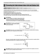
... to the indoor unit by connecting the wires to change without notice. are the same as the fixture. 30 Multi type Air Conditioner The circuit diagram is not subject to change without notice. • Be sure to connect wires according to the indoor and outdoor unit should be complied with the... on the inside of the Outdoor Unit control cover. AWG14 Line voltage (208~230V) GN/YL 20mm The power connecting cable connected to the wiring diagram. • Connect the wires firmly, so that the color of the wires of the outdoor unit and the terminal No. Connecting the Cable between Indoor...
... to the indoor unit by connecting the wires to change without notice. are the same as the fixture. 30 Multi type Air Conditioner The circuit diagram is not subject to change without notice. • Be sure to connect wires according to the indoor and outdoor unit should be complied with the... on the inside of the Outdoor Unit control cover. AWG14 Line voltage (208~230V) GN/YL 20mm The power connecting cable connected to the wiring diagram. • Connect the wires firmly, so that the color of the wires of the outdoor unit and the terminal No. Connecting the Cable between Indoor...

Service Manual
Page 55
Service Manual 55 Schematic Diagram STEPPING MOTOR SUB PCB ASM STEPPING MOTOR STEPPING MOTOR LED2 SLEEP LED3 TIMER LED4 DEFROST LED1 ON/OFF 4(f) a 11 3(a) 22 b f 1(g) 33 g 9(b) 4 4 6(d) c e 55 7(e) 66 8(c) d 77 10 5 ...
Service Manual 55 Schematic Diagram STEPPING MOTOR SUB PCB ASM STEPPING MOTOR STEPPING MOTOR LED2 SLEEP LED3 TIMER LED4 DEFROST LED1 ON/OFF 4(f) a 11 3(a) 22 b f 1(g) 33 g 9(b) 4 4 6(d) c e 55 7(e) 66 8(c) d 77 10 5 ...

Service Manual
Page 58
A2UH243FA0(LMU240HE) 2. Outdoor Unit 1. A2UC243FA0(LMU240CE) 58 Multi type Air Conditioner Schematic Diagram Wiring Diagram 1. Room Type Indoor Unit -S4/SE chassis 2. Art Cool Type Indoor Unit 3.
A2UH243FA0(LMU240HE) 2. Outdoor Unit 1. A2UC243FA0(LMU240CE) 58 Multi type Air Conditioner Schematic Diagram Wiring Diagram 1. Room Type Indoor Unit -S4/SE chassis 2. Art Cool Type Indoor Unit 3.

Service Manual
Page 59
Indoor Unit MAIN P.C.B ASM 1) Split Type • TOP VIEW Schematic Diagram PCB :6870A90409B ASSY :6871A20771 6871A20782 • BOTTOM VIEW Service Manual 59 Components Locations 1.
Indoor Unit MAIN P.C.B ASM 1) Split Type • TOP VIEW Schematic Diagram PCB :6870A90409B ASSY :6871A20771 6871A20782 • BOTTOM VIEW Service Manual 59 Components Locations 1.

Service Manual
Page 64
Troubleshooting Guide Troubleshooting Guide Refrigeration Cycle Diagram 1. Sensor Air Sensor A-Room B-Room Eva. Sensor Ø 6.35 Acc. A2UC243FA0 (LMU240CE) Air Sensor Sensor 64 Multi type Air Conditioner C/V2 C/V1 Th2 Th1 Cons. Comp (GK141K) LEV-B LEV-A LEV 15RC strainer 2. Comp (GK094K) Cons. A2UH243FA0(LMU240HE) Ø 9.52 strainer R/Valve 5220AR3228E S/W Eva.
Troubleshooting Guide Troubleshooting Guide Refrigeration Cycle Diagram 1. Sensor Air Sensor A-Room B-Room Eva. Sensor Ø 6.35 Acc. A2UC243FA0 (LMU240CE) Air Sensor Sensor 64 Multi type Air Conditioner C/V2 C/V1 Th2 Th1 Cons. Comp (GK141K) LEV-B LEV-A LEV 15RC strainer 2. Comp (GK094K) Cons. A2UH243FA0(LMU240HE) Ø 9.52 strainer R/Valve 5220AR3228E S/W Eva.
Service Manual
Page 67
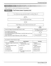
... 67 Does "Beeping" sound is O.K. • Check CN-DISP1 The operation check of main power. • The voltage applied to electronic contorol device drawing & schematic diagram. Ass'y (Fuse, Noise Filter, Power Transformer, IC01D, IC02D, etc.) YES • Primarily, the operating condi- Troubleshooting Guide Turn off the main power and wait until...
... 67 Does "Beeping" sound is O.K. • Check CN-DISP1 The operation check of main power. • The voltage applied to electronic contorol device drawing & schematic diagram. Ass'y (Fuse, Noise Filter, Power Transformer, IC01D, IC02D, etc.) YES • Primarily, the operating condi- Troubleshooting Guide Turn off the main power and wait until...
Service Manual
Page 69
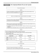
...(1K), Micom(pin No. 74 , 75 , 76 , 77 ). • Check the Indoor temperature sensor is less than one of Outdoor side. Check the electrical wiring diagram of the Indoor temperature by setting the disired temperature of the remote controller is disconnected or not (about 10K at least. Operate Cooling Mode by...
...(1K), Micom(pin No. 74 , 75 , 76 , 77 ). • Check the Indoor temperature sensor is less than one of Outdoor side. Check the electrical wiring diagram of the Indoor temperature by setting the disired temperature of the remote controller is disconnected or not (about 10K at least. Operate Cooling Mode by...


