

Service Manual
Page 55
Service Manual 55 Schematic Diagram STEPPING MOTOR SUB PCB ASM STEPPING MOTOR STEPPING MOTOR LED2 SLEEP LED3 TIMER LED4 DEFROST LED1 ON/OFF 4(f) a 11 3(a) 22 b f 1(g) 33 g 9(b) 4 4 6(d) c e 55 7(e) 66 8(c) d 77 10 5 Digit2 Digit1 88 99 ...
Service Manual 55 Schematic Diagram STEPPING MOTOR SUB PCB ASM STEPPING MOTOR STEPPING MOTOR LED2 SLEEP LED3 TIMER LED4 DEFROST LED1 ON/OFF 4(f) a 11 3(a) 22 b f 1(g) 33 g 9(b) 4 4 6(d) c e 55 7(e) 66 8(c) d 77 10 5 Digit2 Digit1 88 99 ...

Service Manual
Page 59
Components Locations 1. Indoor Unit MAIN P.C.B ASM 1) Split Type • TOP VIEW Schematic Diagram PCB :6870A90409B ASSY :6871A20771 6871A20782 • BOTTOM VIEW Service Manual 59
Components Locations 1. Indoor Unit MAIN P.C.B ASM 1) Split Type • TOP VIEW Schematic Diagram PCB :6870A90409B ASSY :6871A20771 6871A20782 • BOTTOM VIEW Service Manual 59
Service Manual
Page 67
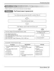
...; 30V : Check the rated voltage 2) 15V ± 1.5V 3) DC12V 4) DC5V 5) The voltage of power trans- Trouble 1 The Product doesn't operate at all. Turn on outdoor PCB is off. NO Check the voltage of power(AC208V/AC230V, 60Hz). • The voltage of main power. • The voltage applied to electronic contorol device...
...; 30V : Check the rated voltage 2) 15V ± 1.5V 3) DC12V 4) DC5V 5) The voltage of power trans- Trouble 1 The Product doesn't operate at all. Turn on outdoor PCB is off. NO Check the voltage of power(AC208V/AC230V, 60Hz). • The voltage of main power. • The voltage applied to electronic contorol device...
Service Manual
Page 69
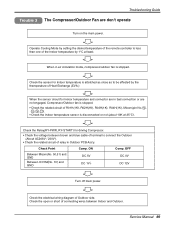
... the Indoor temperature sensor is attatched as close as to connect the Outdoor (About AC208V / 230V). • Check the related circuit of relay in Outdoor PCB Ass'y. Check the sensor for Indoor temperature is disconnected or not (about 10K at least. OFF DC 0V DC 12V Turn off main power.
... the Indoor temperature sensor is attatched as close as to connect the Outdoor (About AC208V / 230V). • Check the related circuit of relay in Outdoor PCB Ass'y. Check the sensor for Indoor temperature is disconnected or not (about 10K at least. OFF DC 0V DC 12V Turn off main power.
Service Manual
Page 72
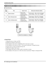
... of the sensor is 10KΩ/5KΩ at 25°C, then sensor is abnormal. ➔ Change the sensor. 5. Plug the sensor on Indoor unit PCB. 2. If the resistance of the sensor is 0 KΩ or ∞, then sensor is normal 4. Estimate the resistance of each sensor. 7. Estimate the voltage of each...°C (plugged) Normal resistor : 5KΩ/ at 25°C (Unplugged) Normal voltage : 2.5Vdc / at 25°C, then sensor is abnormal. ➔ Repair or Change the PCB 72 Multi type Air Conditioner Unplug the sensor on Indoor unit...
... of the sensor is 10KΩ/5KΩ at 25°C, then sensor is abnormal. ➔ Change the sensor. 5. Plug the sensor on Indoor unit PCB. 2. If the resistance of the sensor is 0 KΩ or ∞, then sensor is normal 4. Estimate the resistance of each sensor. 7. Estimate the voltage of each...°C (plugged) Normal resistor : 5KΩ/ at 25°C (Unplugged) Normal voltage : 2.5Vdc / at 25°C, then sensor is abnormal. ➔ Repair or Change the PCB 72 Multi type Air Conditioner Unplug the sensor on Indoor unit...
Service Manual
Page 73
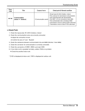
... wire of "Live", "Neutral". 3. Check the connection of GND1, GND2, and main GND. 6. If one indoor unit is operated normally, outdoor PCB is no problem. ➔ Check the another indoor unit. * CH05 is displayed at indoor unit, CH53 is correctly connected. 5. Service Manual 73... is not connected at main GND. • The communication line is shorted at GND. • Transmission circuit of outdoor PCB is abnormal. • Transmission circuit of indoor PCB is abnormal. ❑ Check Point 1. Error code Title 05 / 53 Communication (Indoor ➔ Outdoor) Troubleshooting Guide Cause ...
... wire of "Live", "Neutral". 3. Check the connection of GND1, GND2, and main GND. 6. If one indoor unit is operated normally, outdoor PCB is no problem. ➔ Check the another indoor unit. * CH05 is displayed at indoor unit, CH53 is correctly connected. 5. Service Manual 73... is not connected at main GND. • The communication line is shorted at GND. • Transmission circuit of outdoor PCB is abnormal. • Transmission circuit of indoor PCB is abnormal. ❑ Check Point 1. Error code Title 05 / 53 Communication (Indoor ➔ Outdoor) Troubleshooting Guide Cause ...
Service Manual
Page 81
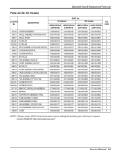
... 3531A10307V 3531A11362A 3531A11362B R 159901 LOUVER,HORIZONTAL 5990A20069A 5990A20069A 5990A20068A 5990A20068A R 147582 LOUVER,VERTICAL 4758A30052A 4758A30052A 4758A30057A 4758A30057A R 146811 MOTOR,DC 4681A20055A 4681A20055A 4681A20055A 4681A20055A R 268712 PCB ASSEMBLY,DISPLAY 6871A20680D 6871A20680F 6871A20680D 6871A20680F R 135516 COVER ASSEMBLY,MOTOR 3551A20156B 3551A20156B 3551A20156B 3551A20156B R 346810 MOTOR,DC 4681AR2295L 4681AR2295L 4681AR2295L 4681AR2295L R 152313 FILTER ASSEMBLY,DEODORIZER...
... 3531A10307V 3531A11362A 3531A11362B R 159901 LOUVER,HORIZONTAL 5990A20069A 5990A20069A 5990A20068A 5990A20068A R 147582 LOUVER,VERTICAL 4758A30052A 4758A30052A 4758A30057A 4758A30057A R 146811 MOTOR,DC 4681A20055A 4681A20055A 4681A20055A 4681A20055A R 268712 PCB ASSEMBLY,DISPLAY 6871A20680D 6871A20680F 6871A20680D 6871A20680F R 135516 COVER ASSEMBLY,MOTOR 3551A20156B 3551A20156B 3551A20156B 3551A20156B R 346810 MOTOR,DC 4681AR2295L 4681AR2295L 4681AR2295L 4681AR2295L R 152313 FILTER ASSEMBLY,DEODORIZER...

Service Manual
Page 83
... MOTOR,DC 4681A20055A 4681A20055A 4681A20055A 4681A20055A R 159830 FILTER ASSEMBLY,AIR CLEANER 5983A20007F 5983A20007F 5983A20007F 5983A20007F R 249951 CASE ASSEMBLY,CONTROL(INDOOR) 4995A20832B 4995A20832A 4995A20832D 4995A20832C R 268714 PCB ASSEMBLY 6871A20387K 6871A20387M 6871A20387M 6871A20387N R 263230-2 THERMISTOR,NTC(ROOM+IN PIPE) 6323A20004N 6323A20004N 6323A20004N 6323A20004N R 263230-1 THERMISTOR,NTC(OUT PIPE) 6323AQ3226T 6323AQ3226T 6323AQ3226T 6323AQ3226T R 267110...
... MOTOR,DC 4681A20055A 4681A20055A 4681A20055A 4681A20055A R 159830 FILTER ASSEMBLY,AIR CLEANER 5983A20007F 5983A20007F 5983A20007F 5983A20007F R 249951 CASE ASSEMBLY,CONTROL(INDOOR) 4995A20832B 4995A20832A 4995A20832D 4995A20832C R 268714 PCB ASSEMBLY 6871A20387K 6871A20387M 6871A20387M 6871A20387N R 263230-2 THERMISTOR,NTC(ROOM+IN PIPE) 6323A20004N 6323A20004N 6323A20004N 6323A20004N R 263230-1 THERMISTOR,NTC(OUT PIPE) 6323AQ3226T 6323AQ3226T 6323AQ3226T 6323AQ3226T R 267110...

Service Manual
Page 85
...Solenoid(Coil Assempy, Reverse) is only for heat pump model. Service Manual 85 Description Part No. SVC A2UH243FA0(LMU240HE) A2UC243FA0 (LMU240CE) CODE 437210 PANEL ASSEMBLY,FRONT(SUB) 1A00197C 1A00197C R 137213-1 PANEL ASSEMBLY,SIDE 1A00202F 1A00202F ...GK094KAA) 2520UGJK2AA(GK094KAA) R 447910 BARRIER ASSEMBLY,OUTDOOR 4791A30004H 4791A30004H R 649950 CASE ASSEMBLY,CONTROL(OUTDOOR) 4995A00002G 4995A00002G R 668711 PCB ASSEMBLY,MAIN 6871A20500B 6871A20500B R 435511 COVER ASSEMBLY,CONTROL(OUTDOOR) 3551A10044E 3551A10044F R WOCZZ-1 CAPACITOR,FILM,BOX 2A00986G 2A00986G R...
...Solenoid(Coil Assempy, Reverse) is only for heat pump model. Service Manual 85 Description Part No. SVC A2UH243FA0(LMU240HE) A2UC243FA0 (LMU240CE) CODE 437210 PANEL ASSEMBLY,FRONT(SUB) 1A00197C 1A00197C R 137213-1 PANEL ASSEMBLY,SIDE 1A00202F 1A00202F ...GK094KAA) 2520UGJK2AA(GK094KAA) R 447910 BARRIER ASSEMBLY,OUTDOOR 4791A30004H 4791A30004H R 649950 CASE ASSEMBLY,CONTROL(OUTDOOR) 4995A00002G 4995A00002G R 668711 PCB ASSEMBLY,MAIN 6871A20500B 6871A20500B R 435511 COVER ASSEMBLY,CONTROL(OUTDOOR) 3551A10044E 3551A10044F R WOCZZ-1 CAPACITOR,FILM,BOX 2A00986G 2A00986G R...
