Service Manual
Page 2
... Disassembly ...49 Indoor Unit...49 Schematic Diagram...54 Electronic Control Device ...54 Wiring Diagram...58 Components Locations...59 Troubleshooting Guide ...64 Refrigeration Cycle Diagram ...64 Self-diagnosis Function ...65 Cycle Troubleshooting Guide...66 Electronic Parts Troubleshooting Guide 67 General Information...72 2-way, 3-way Valve ...78 Exploded View & Replacement Parts List 82 Indoor Unit...
... Disassembly ...49 Indoor Unit...49 Schematic Diagram...54 Electronic Control Device ...54 Wiring Diagram...58 Components Locations...59 Troubleshooting Guide ...64 Refrigeration Cycle Diagram ...64 Self-diagnosis Function ...65 Cycle Troubleshooting Guide...66 Electronic Parts Troubleshooting Guide 67 General Information...72 2-way, 3-way Valve ...78 Exploded View & Replacement Parts List 82 Indoor Unit...

Service Manual
Page 64
Comp (GK094K) Cons. A2UC243FA0 (LMU240CE) Air Sensor Sensor 64 Multi type Air Conditioner Sensor Air Sensor A-Room B-Room Eva. C/V2 C/V1 Th2 Th1 Cons. Troubleshooting Guide Troubleshooting Guide Refrigeration Cycle Diagram 1. Sensor Ø 6.35 Acc. A2UH243FA0(LMU240HE) Ø 9.52 strainer R/Valve 5220AR3228E S/W Eva. Comp (GK141K) LEV-B LEV-A LEV 15RC strainer 2.
Comp (GK094K) Cons. A2UC243FA0 (LMU240CE) Air Sensor Sensor 64 Multi type Air Conditioner Sensor Air Sensor A-Room B-Room Eva. C/V2 C/V1 Th2 Th1 Cons. Troubleshooting Guide Troubleshooting Guide Refrigeration Cycle Diagram 1. Sensor Ø 6.35 Acc. A2UH243FA0(LMU240HE) Ø 9.52 strainer R/Valve 5220AR3228E S/W Eva. Comp (GK141K) LEV-B LEV-A LEV 15RC strainer 2.
Service Manual
Page 65
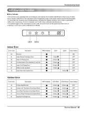
...(Open/Short) 51 Capcity Error(High/Low) 3 times 3 times OFF 4 times 4 times OFF 4 times 5 times OFF 4 times 7 times OFF 5 times 1 times OFF Service Manual 65 Troubleshooting Guide Self-diagnosis Function I Error Indicator • The function is to self-diagnoisis airconditioner and express the troubles identifically if there is any trouble. •...
...(Open/Short) 51 Capcity Error(High/Low) 3 times 3 times OFF 4 times 4 times OFF 4 times 5 times OFF 4 times 7 times OFF 5 times 1 times OFF Service Manual 65 Troubleshooting Guide Self-diagnosis Function I Error Indicator • The function is to self-diagnoisis airconditioner and express the troubles identifically if there is any trouble. •...

Service Manual
Page 66
...(Leakage) Clogging Description Current is low. difference Current : approx. 0°C(32°F) : less than 80% of rated current Refrigerant leakage Clog of refrigerant Temp. Troubleshooting Guide Cycle Troubleshooting Guide Trouble analysis 1. difference : over 8°C(46.4°F) Normal Notice: Temperature difference between intake and discharge air, and operating current. Check temperature and pressure...
...(Leakage) Clogging Description Current is low. difference Current : approx. 0°C(32°F) : less than 80% of rated current Refrigerant leakage Clog of refrigerant Temp. Troubleshooting Guide Cycle Troubleshooting Guide Trouble analysis 1. difference : over 8°C(46.4°F) Normal Notice: Temperature difference between intake and discharge air, and operating current. Check temperature and pressure...
Service Manual
Page 67
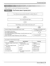
... 29 : DC4.5V↑ Remedy 1) Replace power transfomer. 2) Replace power transfomer. 3) Replace IC01D. 4) Replace IC02D. 5) Replace IC01A. Troubleshooting Guide Turn off . Turn on outdoor PCB is made from the indoor unit? Electronic Parts Troubleshooting Guide ❇ Refer to the unit. • The connecting method of Indoor/Outdoor connecting cable (each color) •...
... 29 : DC4.5V↑ Remedy 1) Replace power transfomer. 2) Replace power transfomer. 3) Replace IC01D. 4) Replace IC02D. 5) Replace IC01A. Troubleshooting Guide Turn off . Turn on outdoor PCB is made from the indoor unit? Electronic Parts Troubleshooting Guide ❇ Refer to the unit. • The connecting method of Indoor/Outdoor connecting cable (each color) •...

Service Manual
Page 68
... in LCD screen, replace battery. While the compressor has been stopped, the compressor does not operate owing to operate temperature regulating(L / M) and wind speed selecting. Troubleshooting Guide Trouble 2 Product doesn't operate with the remote controller. When the compressor stopped Indoor Fan is impossible to the delaying function for 3 minutes after stopped...
... in LCD screen, replace battery. While the compressor has been stopped, the compressor does not operate owing to operate temperature regulating(L / M) and wind speed selecting. Troubleshooting Guide Trouble 2 Product doesn't operate with the remote controller. When the compressor stopped Indoor Fan is impossible to the delaying function for 3 minutes after stopped...
Service Manual
Page 69
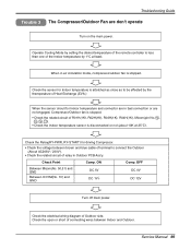
OFF DC 0V DC 12V Turn off main power. Troubleshooting Guide Trouble 3 The Compressor/Outdoor Fan are not engaged, Compressor/Outdoor fan is stopped. • Check the related circuit of R01H(1K), R02H(1K), R03H(...
OFF DC 0V DC 12V Turn off main power. Troubleshooting Guide Trouble 3 The Compressor/Outdoor Fan are not engaged, Compressor/Outdoor fan is stopped. • Check the related circuit of R01H(1K), R02H(1K), R03H(...
Service Manual
Page 70
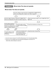
Troubleshooting Guide Trouble 4 When indoor Fan does not operate. Check the interference of Indoor Fan Indoor Fan may be stopped when Indoor pipe(coil) termperature is ...
Troubleshooting Guide Trouble 4 When indoor Fan does not operate. Check the interference of Indoor Fan Indoor Fan may be stopped when Indoor pipe(coil) termperature is ...

Service Manual
Page 71
... interfering parts in the rotation radial of the Vertical Louver Service Manual 71 Between 1 , 2 , 3 , 4 and 5 of IC01M - Between 60 , 61 , 62 and 63 of IC01M - Troubleshooting Guide Trouble 5 When the louver does not operate. Between 2 , 3 , 4 and 5 of CN-UP/DOWN If there are no problems after above checks • Confirm the...
... interfering parts in the rotation radial of the Vertical Louver Service Manual 71 Between 1 , 2 , 3 , 4 and 5 of IC01M - Between 60 , 61 , 62 and 63 of IC01M - Troubleshooting Guide Trouble 5 When the louver does not operate. Between 2 , 3 , 4 and 5 of CN-UP/DOWN If there are no problems after above checks • Confirm the...
Service Manual
Page 72
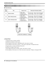
Plug the sensor on Indoor unit PCB. 2. Troubleshooting Guide Error Code I Trouble Shooting Error code Title 01 Indoor air sensor 02 Indoor inlet pipe sensor 06 Indoor outlet pipe sensor Cause of the ...
Plug the sensor on Indoor unit PCB. 2. Troubleshooting Guide Error Code I Trouble Shooting Error code Title 01 Indoor air sensor 02 Indoor inlet pipe sensor 06 Indoor outlet pipe sensor Cause of the ...
Service Manual
Page 73
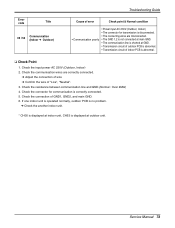
Service Manual 73 Check the resistance between communication line and GND.(Normal : Over 2MΩ) 4. Error code Title 05 / 53 Communication (Indoor ➔ Outdoor) Troubleshooting Guide Cause of error Check point & Normal condition • Power input AC 230V.(Outdoor, Indoor) • The connector for communication is correctly connected. 5. If one ...
Service Manual 73 Check the resistance between communication line and GND.(Normal : Over 2MΩ) 4. Error code Title 05 / 53 Communication (Indoor ➔ Outdoor) Troubleshooting Guide Cause of error Check point & Normal condition • Power input AC 230V.(Outdoor, Indoor) • The connector for communication is correctly connected. 5. If one ...

Service Manual
Page 74
Troubleshooting Guide Error code Title 33 D-Pipe Temp. Check the SVC V/V open . 115°C(239°F) 100°C(212°F) 95°C(203°F) COMP OFF ...
Troubleshooting Guide Error code Title 33 D-Pipe Temp. Check the SVC V/V open . 115°C(239°F) 100°C(212°F) 95°C(203°F) COMP OFF ...
Service Manual
Page 75
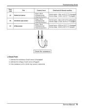
...;C(77°F) (plugged) Ω Ω Check the resistance ❑ Check Point 1. Error code Title 44 Outdoor air sensor 45 Condensor pipe sensor 47 D-Pipe sensor Troubleshooting Guide Cause of each sensor.(Plugged) 3. Estimate the voltage of each sensor.(Unplugged) 2.
...;C(77°F) (plugged) Ω Ω Check the resistance ❑ Check Point 1. Error code Title 44 Outdoor air sensor 45 Condensor pipe sensor 47 D-Pipe sensor Troubleshooting Guide Cause of each sensor.(Plugged) 3. Estimate the voltage of each sensor.(Unplugged) 2.
