Owners Manual
Page 44
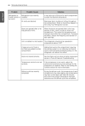
...and confirm the proper temperature has been restored once the defrost cycle has completed. Rearrange items to allow air to the Airflow diagram in the Using Your Refrigerator section. Refer to flow throughout the compartment. Adding food warms the compartment requiring the cooling system to... is installed. Defrost cycle has recently completed. A large amount of food or hot food was recently Freezer section is installed in Parts & Features Troubleshooting. Doors not closed correctly. Solutions It may take up to 24 hours for each compartment may raise slightly and ...
...and confirm the proper temperature has been restored once the defrost cycle has completed. Rearrange items to allow air to the Airflow diagram in the Using Your Refrigerator section. Refer to flow throughout the compartment. Adding food warms the compartment requiring the cooling system to... is installed. Defrost cycle has recently completed. A large amount of food or hot food was recently Freezer section is installed in Parts & Features Troubleshooting. Doors not closed correctly. Solutions It may take up to 24 hours for each compartment may raise slightly and ...
Service Manual
Page 2
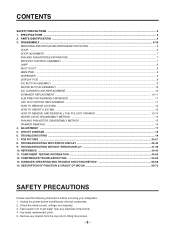
...caution not to get water near any objects from the top prior to tilting the product. - 2- Remove any electrical components. 4. PARTS IDENTIFICATION ...4 3. DISASSEMBLY ...5-16 REMOVING AND REPLACING REFRIGERATOR DOORS 5 DOOR ...6 DOOR ALIGNMENT ...7 FAN AND FAN MOTOR(EVAPORATOR) ...7 DEFROST...MOTOR DISASSEMBLY METHOD ...15 DRAWER REMOVAL ...16 4. CONTENTS SAFETY PRECAUTIONS ...2 1. REFERENCE ...40-43 11. SPECIFICATIONS ...3 2. CIRCUIT DIAGRAM ...18 6. PCB PICTURE ...20-21 8. COMPONENT TESTING INFORMATION ...44-52 12. TROUBLESHOOTING WITH ERROR DISPLAY ...22-30 9. ...
...caution not to get water near any objects from the top prior to tilting the product. - 2- Remove any electrical components. 4. PARTS IDENTIFICATION ...4 3. DISASSEMBLY ...5-16 REMOVING AND REPLACING REFRIGERATOR DOORS 5 DOOR ...6 DOOR ALIGNMENT ...7 FAN AND FAN MOTOR(EVAPORATOR) ...7 DEFROST...MOTOR DISASSEMBLY METHOD ...15 DRAWER REMOVAL ...16 4. CONTENTS SAFETY PRECAUTIONS ...2 1. REFERENCE ...40-43 11. SPECIFICATIONS ...3 2. CIRCUIT DIAGRAM ...18 6. PCB PICTURE ...20-21 8. COMPONENT TESTING INFORMATION ...44-52 12. TROUBLESHOOTING WITH ERROR DISPLAY ...22-30 9. ...


